

Usually, a very hot product is considered a problem for a typical mechanical seal. This is particularly true for refinery applications, where product temperatures reaching 700 F (or even more) are not unusual. Cooling flush plans, special seal materials, etc., are used in such cases, clearly challenging and not inexpensive propositions. However, if a pump operates continuously and a product remains relatively clean, most seal manufacturers have learned how to combat many of these challenges and developed seals that can withstand elevated temperatures.
.jpg) IMAGE 1: Leaky seal after a few weeks (Images courtesy of the author)
IMAGE 1: Leaky seal after a few weeks (Images courtesy of the author)But each rule has exceptions, and I am covering one of these exceptions in this column—one that I encountered on a troubleshooting assignment at a refinery that reported continual seal failures every few weeks.
This single-stage double suction pump handled hot (700 F), clean oil (0.8 specific gravity [SG], 3.5 centipoise [cP]), with the best efficiency point (BEP) being 1,400 gallons per minute (gpm), 750 feet head. These were the conditions reported at the beginning of the analysis.
On a first glance, nothing seemed too alarming. So, why was there a problem?
Upon visiting the plant, I gleaned a few more tidbits of information. First, I found that net positive suction head available (NPSHa) was sufficiently higher than required: 20 feet NPSHa versus 12 feet net positive suction head required (NPSHr). This was a good sign. However, when calculating suction specific speed (Nss) for this pump running at 3,000 revolutions per minute (rpm), the Nss value was over 12,000—a warning sign. As we know, too much of a good thing may not be good at all. The question is not how much extra available NPSH you have, but does the pump have the NPSHr too low.
Indeed, as widely known and published in the literature and researched by the pump users, a value of Nss over 9,500 spells trouble, as susceptibility of such pumps to suction recirculation becomes pronounced, thus limiting such pumps to operate close to the BEP, and not significantly outside of it, as is a typically acceptable practice of the American Petroleum Institute (API) pump users’ community. API does not recommend Nss to exceed 9,500, as mean time between failures (MTBF) is well documented to exponentially decrease (failures increase), as shown in Image 2.
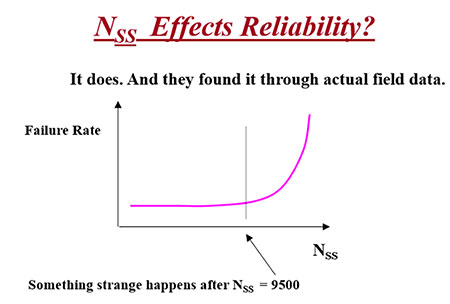 IMAGE 2: How specific suction speed affects a pump’s reliability
API 610 recommends allowable operating flow to be between 60 and 120 percent of the BEP, and it is preferred between 70 and 110 percent of the BEP, even for impeller designs with Nss of 9,500. For the higher value of Nss, this range should be reduced even further, due to suction recirculation creating significant flow instabilities, causing possible failure of seals and bearings.
The next step was to find exactly where (i.e., what flow) this pump operates? As is often the case, it is wise to talk to the operators. Indeed, it turned out that the majority of time this pump operated at well below a 50 percent flow range—clearly another warning sign. Deflection of the shaft, caused by the high radial thrust at low flow, causes seal faces to deflect and leakage to occur.
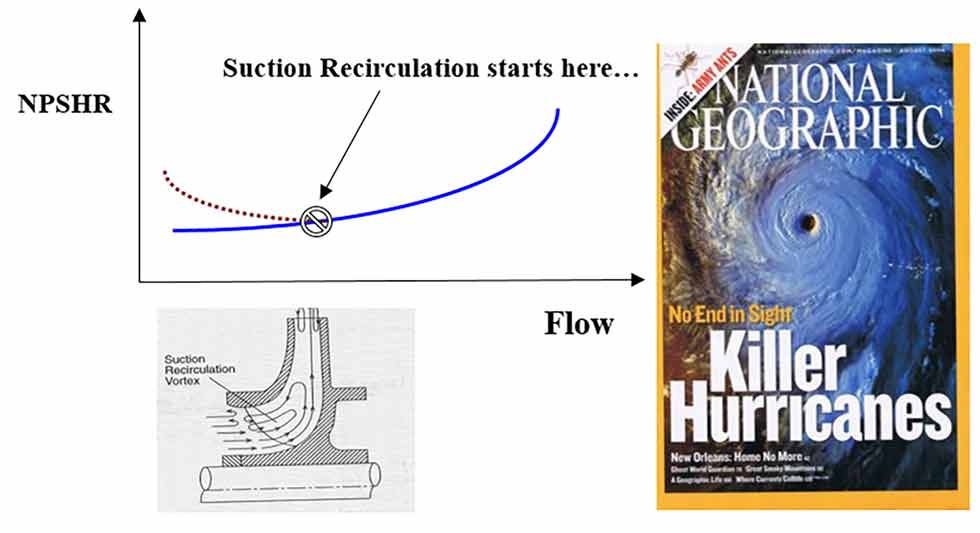 IMAGE 3: Low flow suction recirculation (magazine analogy for illustration)
Yet, even with such low flow operation, the seal failures rate seemed too frequent, and so we continued looking for more clues.
The rated viscosity of the product seemed OK at 3.5 cP. The rated temperature was 700 F—but what was the actual temperature? The operator’s answer was “it varies,” reaching as low as 500 F. I was given three lab test points for this fluid (at 220, 400 and 640 F) and made my own graph, as shown in Image 5.
If the graph was correct, viscosity could be as high as 1,000 cP at the actual operating conditions. Checking with my friends in the mechanical seal manufacturers community, I was told that 1,000 cP (per se) is not particularly problematic for a seal, and that a typical seal could easily handle cP values as high as 3,000 cP, provided all other conditions in the seal chamber are good.
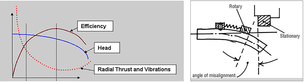 IMAGE 4: (left and right) Shaft deflection and seal faces opening at low flow operation
So, the next questions: Are there other “bad actors” in the seal chamber that are killing it? Is it flushed properly? Are there any solids in pumpage?
The pump was originally designed with API Plan 11 seal flush and Plan 62 quench. However, Plan 11 was never implemented, and the seal chamber was dead headed (Plan 2), although quenching (Plan 62) was used. This is unusual, but still was not enough to explain the rate of failures, in my view.
What I learned next was the nature of this pump prewarming after the repairs and startup procedure. While doing a proper prewarming (for nearly two hours) by the externally flushed liquid, the product did not properly vent. At ambient temperature (prior to startup), the product would be tar-like, with viscosity skyrocketing, as can be estimated from Image 5. More proof of that was the black tar film sitting all over the outside parts of the skid and pipes.
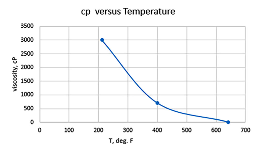 IMAGE 5: Viscosity vs. temperature
It was then possible that cycling cooling and heating (due to product temperature variations), and perhaps aggravated by the starts/stops, might be creating rough, tar-like particulates (as evident from the solidified residue on the pump body), which would further worsen the problem of leak past the seal faces.
During idle time, cooled product would form tar particulates at the seal faces areas, and subsequent starts
(especially with operation at low flow, where seal faces are defected as explained earlier) would drag particles to the seal faces—opened, to begin with—by the radial load at low flow and a cause eventual failure.
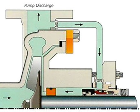 IMAGE 6: Typical seal flush plan (Plan 11)
Putting together our findings, the following conclusions could be drawn:
- The first issue is low flow operation, which causes shaft deflection and opening of the seal faces.
- Low temperature (high viscosity) during pump idle time (and perhaps during occasional low temperature operation) would cause solidification of product, which likely remains (at least some of it) inside the seal chamber, setting at the seal faces and causing them to be further jammed open and leak or fail.
- The impeller design is not per API recommendations of the low Nss (Nss < 9,500), and the higher value aggravates the problem of suction recirculation and seal issues associated with that.
- “No flush plan” (Plan 2) is an additional problem. The seal chamber needs to be flushed with the external clean supply (Plan 32), or at least Plan 11 with the assured way not to clog the flush line.
Let me know your feedback, questions or suggestions per your own experience. I will discuss your input in a future issue.
