
Consider temperature, volume and liquid feed control
01/04/2018
A spray dryer is a device in which a specific solution or suspension of solids and liquids is fed through spray nozzles into a drying chamber. There, it is mixed with heated air or gas to accomplish evaporation of the carrier liquid so the solids of a particular size and shape remain as the finished product.
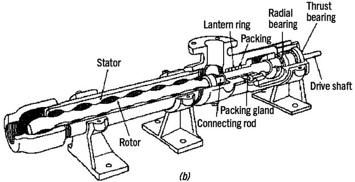 Figure 1. Typical progressing cavity pump. (Images and graphics courtesy of FELUWA Pumps)
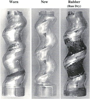 Figure 2. Worn rotor
- capacity
- pressure
- viscosity
- slurry shear sensitivity
- solids characteristics
- abrasiveness
- sticky/agglomerating
- attrition sensitivity
- liquid characteristics
- corrosiveness
- temperature
- net positive suction head (NPSH)
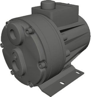 Figure 3. Typical flat diaphragm pumps.
Progressing Cavity Pumps
Progressing cavity pumps (PCPs), also known as progressive cavity pumps, consist of a single helical metal rotor rotating inside a double helical elastomeric stator, which inherently forms cavities in the portions of the double helix that are not occupied by the rotor. As the rotor turns, the cavity progresses through the stator. The steel rotor seals against the elastomeric stator resulting in a pumping action that is similar to a piston pump, which is always in its forward stroke. This type of pump offers the perceived benefit of no pulsations, no check valves, relatively small installation footprint and low initial cost. However, in abrasive duties such as spray dryer feeding, there can be a high rate of wear—first in the elastomeric stator and then in the steel rotor. As the elastomeric stator begins to wear, the seal between rotor and stator is compromised, which results in slip of high pressure slurry back to the lower pressure suction. This slip accelerates the wear and pump performance diminishes until the parts are replaced. Because this is a rotary motion pump, shaft seals or packing are required to keep the process fluid from leaking out of the rotating input shaft. Additionally, universal joints are required to connect the concentric input shaft to the eccentric motion helical rotor. Since these universal joints operate within the solids-laden process fluid, they can also be problematic. The maintenance costs of PCPs can eclipse the low initial costs very quickly.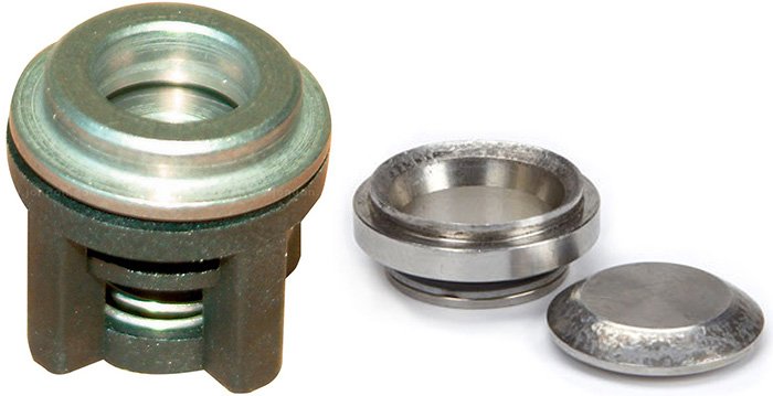 Figure 4. Typical check valve component.
Flat Diaphragm Pumps
Flat diaphragm pumps use an elastomeric diaphragm typically actuated by a propellant fluid, which is actuated by a piston. Slurry is segregated from the hydraulic fluid via the diaphragm and directed in and out of the pump by means of metal check valves. This style of pump is considered a sealless design. Pulsations generated by this reciprocating pump are controlled to a process acceptable level via a downstream pulsation dampener.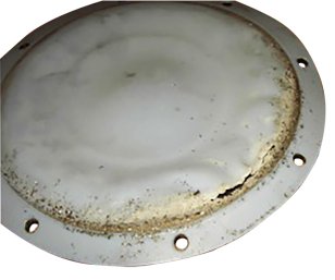 Figure 5. Ruptured/torn diaphragm
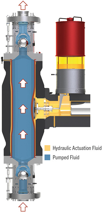 Figure 6. Double hose-diaphragm pump
Double Hose-Diaphragm Pumps
Double hose-diaphragm pumps use a hose within a hose in place of a flat diaphragm. During operation, both hose-diaphragms are hydraulically coupled and compressed by propellant fluid, which is pressurized by a piston. The outer hose then transfers that pressure through the inner hose into the slurry. The slurry is directed in and out of the pump via large abrasive-resistant coated steel ball–type slurry check valves. Pulsations generated by this reciprocating pump are controlled to a process-acceptable level via a downstream pulsation dampener. Typical operating speeds of this pump type are less than 60 strokes per minute. While this increases required installation footprint, the lower speed usually equates to much longer life of the wearing components. As a rule of thumb, wear rate is a function of the square of the difference in speed. Therefore, as a general rule with all other variables held constant, a pump operating at half the speed of another will have a service life four times the other. This style of pump is also considered a sealless design. Because the hose-diaphragm is concentrically compressed due to its inherent design, it is subject to lower mechanical stress, which results in a longer life.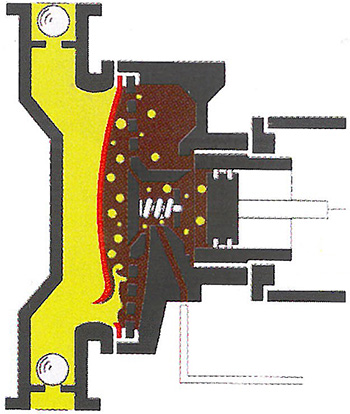 Figure 7. Hose-diaphragm clamping.
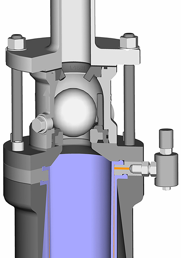 Figure 8. Pressure switch at double hose-diaphragm.
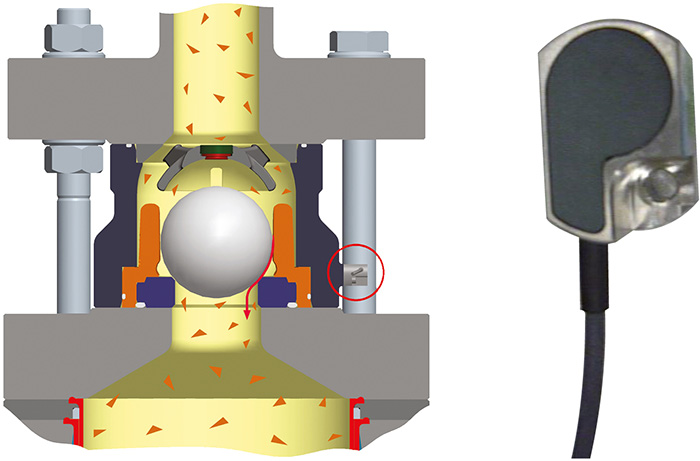 Figure 9. Valve performance monitoring system provides predictive maintenance.