

Centrifugal pumps are commonly used to supply cooling water to the common auxiliary heat exchangers (HEs) of a power plant, such as lube oil coolers, an electric generator’s air or hydrogen coolers, atomizing air coolers (for the combined cycle plant that fires liquid distillate oil in the gas turbines) and inter- and after-coolers of the air compressors.
The hot water from these HEs usually cools in the cooling towers in an open-loop (recirculating) cooling water system. However, in a closed-loop cooling water system, the hot water cools in the common fin-fan air coolers and returns to the suction of the recirculating pump to close the piping loop. The net positive suction head available (NPSHa) for such recirculating pumps may not be higher than the net positive suction head required (NPSHr). An expansion tank usually finds its application in achieving an NPSHa higher than the NPSHr (where it is sometimes referred to as head tank) and/or in accommodating the swell of the system’s water volume due to temperature changes in the heat exchangers above ambient (where it is often referred to as expansion tank). For low-pressure, American Society of Mechanical Engineers (ASME)-approved tanks, the head tank provides direct suction to the closed-loop recirculating pump and accommodates the mild pressure of the returning water stream. The expansion tank being the only accommodating swell of the system water volume could be an atmospheric tank per Underwriters Laboratories (UL) 142.
Without a head or expansion tank, starting the centrifugal pump from standstill condition in a closed-loop cooling water system makes it a challenge to achieve an NPSHa higher than the NPSHr. The layout of a returning water suction piping inverted ‘U’ loop from a fin-fan cooler outlet directly to the suction of the recirculating pump (in the case of expansion tanks) or vertically down with fewer minimum bends for the recirculating pump (in the case of ASME tanks) is critical in ensuring the NPSHa is higher than required NPSHr by an adequate margin at startup. If the circulating water quality is compatible city water and not demineralized water, the open-air vent on the installed elevated expansion tank or head tank will facilitate an adequate margin in NPSHa over NPSHr, complying with the relevant stipulation in the pump design standard.
If the recirculating pump directly sucks from the head tank, NPSHa would be the entire suction head and atmospheric head acting on the water’s surface in the head tank minus vapor pressure of water and frictional losses in the suction header pipe, ignoring positive velocity head.
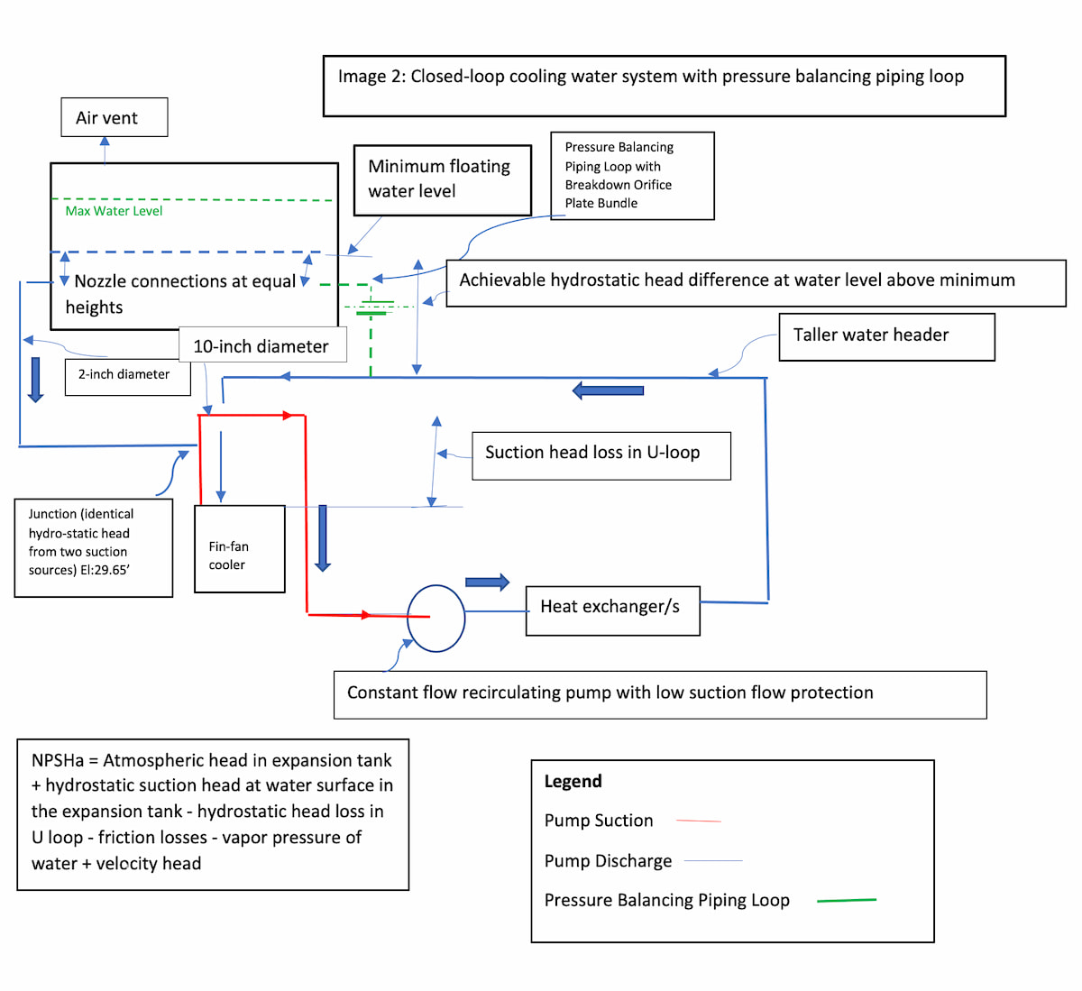
In the case of atmospheric tanks (per UL142), to benefit from an increase in NPSHa, the expansion tank must be located at a higher elevation than the suction (return water) header pipe for the recirculating pump. At pump standstill condition, this may cause the hydrostatic head at the point of merger (junction) between the header pipe from the expansion tank and the pump’s return water header to be greater than the hydrostatic head available from the return water header pipe, causing gravity flow or pump suction flow to occur when the pump kicks in. It is important to recognize that the hydrostatic head at the junction between the two suction sources at standstill condition must be the same to prevent gravity flow occurring when the pump kicks in. The flow pressure at the exit of the header pipe from the expansion tank must not drop too far below the atmospheric pressure (due to a greater area of exposure to return water header), as this would decrease NPSH significantly.
Also, if the hydrostatic head at the junction of the expansion tank is greater than the hydrostatic head of the return water header, the expanded system liquid volume will not easily return to the expansion tank. A pressure balancing piping loop with a breakdown orifice plate bundle connecting the pump’s discharge header pipe with the expansion tank below its minimum water surface would equalize the hydrostatic head at standstill condition at the junction of the two suction sources by availing the hydrostatic head between the water surface at equal height in the expansion tank and the taller discharge header pipe. When the pump “pulls in,” this hydraulic connection will prevent suction flow from the expansion tank, causing full flow to only occur from the return water header connected to pump suction at prevailing absolute hydrostatic head above NPSHr in the header pipe. This identical hydrostatic head at the junction between the two suction sources at standstill condition will also cause the swell of the system liquid volume to rise into the expansion tank when the pump has stopped running.
Having nozzle connections at equal heights below the water’s surface and providing identical orientation (horizontal preferred) in the expansion tank (one each from suction and discharge header pipe) will ensure the hydrostatic head at the junction of both sources is equal regardless of the prevailing water level in the expansion tank above the nozzle connections.
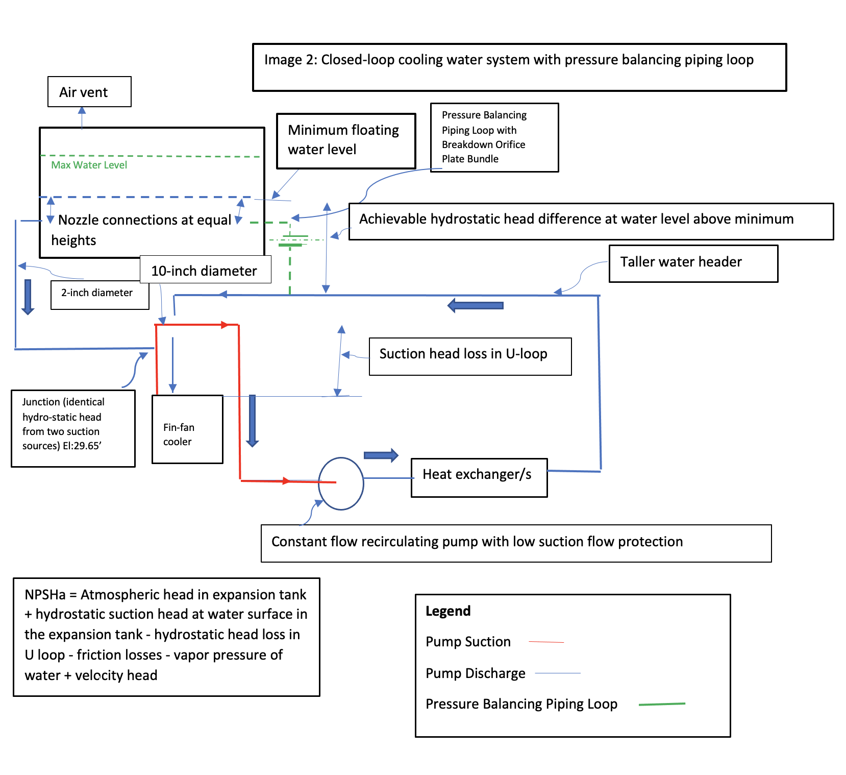
The merit of connecting the expansion tank to the return water header via a small diameter header pipe (per UL142) is in its use of the recirculating nature of constant flow closed-loop cooling systems by avoiding the dedicated individual pump’s discharge recirculating water piping loop. However, users will have to accept the extra margin between the NPSHa and NPSHr due to the typical inverted U-suction piping loop, which can be avoided in the case of direct and vertical pump suction piping being used in an ASME-approved tank.
Even though both ASME-approved and UL142-approved tank options would meet the stipulation of pump design standards in achieving an NPSHa higher than NPSHr by the minimum required margin, the ease of a vertical suction piping layout as well as the additional margin between NPSHa and NPSHr in the case of ASME-approved tanks may find favor in comparison to the inverted U-loop suction piping and need for additional pressure balancing of the piping loop found in UL142-approved tanks.
