
Pumps are one of the largest users of mechanical seals. As the name suggests, mechanical seals are contact-type seals, differentiated from aerodynamic or labyrinth noncontact seals. Mechanical seals are also characterized as balanced or unbalanced. This refers to what percentage of, if any, process pressure can come around behind the stationary seal face. If the seal face is not pushed against the spinning face (as in a pusher-type seal) or process fluid at the pressure that needs to be sealed is not allowed to get behind the seal face, the process pressure would blow the seal face back and open. The seal designer needs to consider all operating conditions to design a seal with the requisite closing force, but not so much force that the unit loading at the dynamic seal face creates too much heat and wear. This is a delicate balance that makes or breaks pump reliability. This article will describe a new or unconventional way to balance the contact forces of the dynamic seal faces by enabling an opening force rather than the conventional way of balancing the closing force, as described above. It does not eliminate the requisite closing force but gives the pump designer and user another knob to turn by allowing unweighting or unloading of the seal faces. It maintains the needed closing force, thus reducing heat and wear while widening the possible operating conditions. Dry gas seals (DGS), often used in compressors, provide an opening force at the seal faces. This force is created by an aerodynamic bearing principle, where fine pumping grooves help encourage gas from the high-pressure process side of the seal, into the gap and across the face of the seal as a noncontact fluid film bearing. As the closing force on the faces goes up, this aerodynamic bearing layer will get thinner but stiffer, as shown by J.S. Stahley (Image 1a).
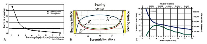 Image 1a. The aerodynamic bearing opening force of a dry gas seal face. The slope of the line is representative of the stiffness at a gap. Note that the gap is in microns. Image 1b. Qualitative plots of fluid-film bearing parameters versus journal eccentricity ratio. Stiffness, K, and damping, D, are minimum when the journal is at the center of the bearing. As the journal nears the bearing surface, stiffness and damping increase dramatically. Image 1c. Lift versus load chart comparing orifice and porous externally pressurized gas bearings. At small gaps orifice bearings collapse but porous bearings behave as dry gas seals and oil bearings. (Images courtesy of New-Seal, Inc.)
Aerodynamic vs. Aerostatic
Externally pressurized aerostatic gas bearings employ a source of pressurized gas, whereas dynamic bearings use the relative motion between the surfaces to generate gap pressure. The externally pressurized technology has at least two fundamental advantages. First, the pressurized gas may be injected between the seal faces in a controlled fashion rather than encouraging the gas into the seal gap with shallow pumping grooves that require motion. This step enables separating the seal faces before rotation starts. Even if the faces are wrung together, they will pop open for zero friction starts and stops when pressure is injected directly between them. Additionally, if the seal is running hot, it is possible with external pressure to increase the pressure to the face of the seal. The gap then would increase proportionally with pressure, but the heat from shear would fall on a cube function of the gap. This gives the operator capability to leverage against heat generation. There is another advantage in compressors in that there is no flow across the face as there is in a DGS. Instead, the highest pressure is between the seal faces, and the external pressure will flow into the atmosphere or vent into one side and into the compressor from the other side. This increases reliability by keeping the process out of the gap. In pumps this may not be an advantage as it can be undesirable to force a compressible gas into a pump. Compressible gases inside of pumps can cause cavitation or air hammer issues. It would be interesting, though, to have a non-contacting or friction-free seal for pumps without the disadvantage of gas flow into the pump process. Could it be possible to have an externally pressurized gas bearing with zero flow?Compensation
All externally pressurized bearings have some sort of compensation—a form of restriction that holds pressure back in reserve. The most common form of compensation is the use of orifices, but there are also groove, step and porous techniques. Compensation enables bearings or seal faces to run close together without touching because the closer they get, the higher the gas pressure between them gets, repelling the faces apart. For example, under a flat orifice compensated gas bearing, the average pressure in the gap will equal the total load on the bearing divided by the face area—this is unit loading. If this source gas pressure is 60 pounds per square inch (psi) and the face has 10 square inches of area and 300 pounds of load, there will be an average of 30 psi in the bearing gap. Typically, the gap is about 0.0003 inches and, because the gap is so small, the flow would only reach about 0.2 standard cubic feet per minute (scfm). Since there is an orifice restrictor just before the gap holding pressure back in reserve, the load increases to 400 pounds, the bearing gap is reduced to about 0.0002 inches, restricting flow through the gap down to 0.1 scfm.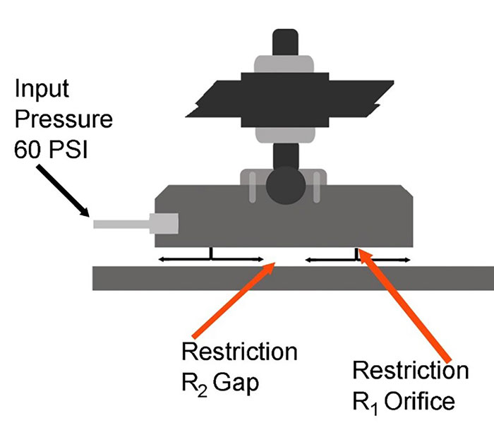 Image 2. This is a cutaway side view of a typical orifice air bearing found in a coordinate measuring machine (CMM).
Orifice vs. Porous Compensation
Orifice compensation is the most widely used form of compensation. A typical orifice may have a hole diameter of 0.010 inches, but since it is feeding a few square inches of area, it is feeding several orders of magnitude more area than itself, so the velocity of the gas can be high. Often, orifices are precisely cut from rubies or sapphires to avoid erosion of the orifice size and so changes the performance of the bearing. Another issue to remember is that at gaps below 0.0002 inches, the area around the orifice starts to choke the flow to the rest of the face, and collapse of the gas film occurs (Image 1c).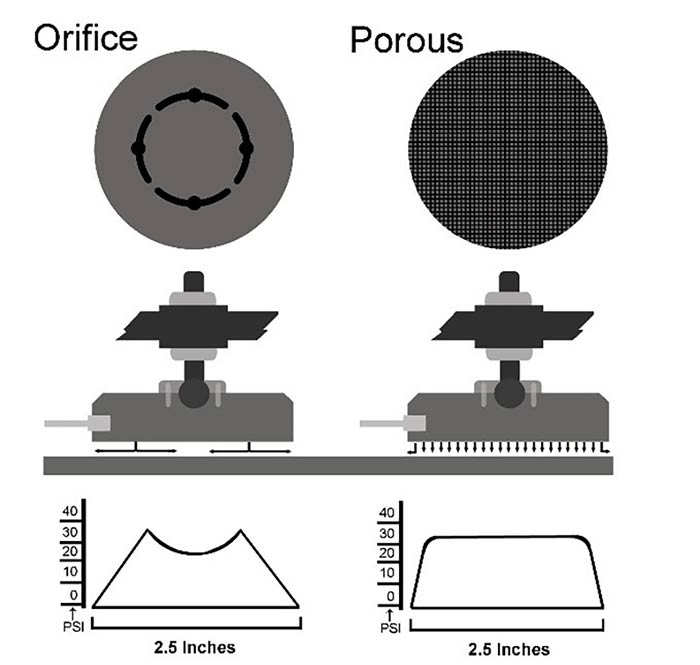 Image 3. Orifice bearings have only the area of the orifices and any grooves for the pressure to establish initial lift. The even pressure profile of porous gas bearings makes them more suited for application to sealing technology.
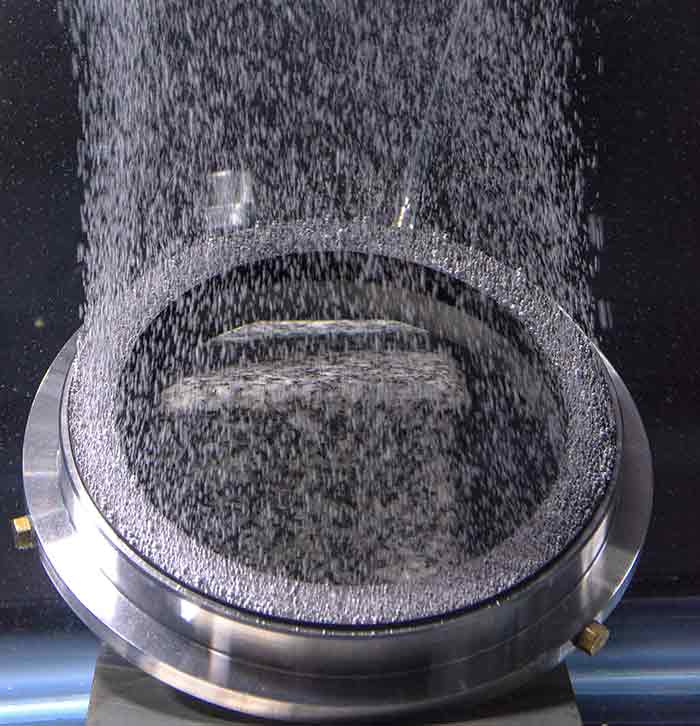 Image 4. A mechanical seal face of porous graphite showing air bleeding out of the flat lapped face. The input pressure may be adjusted to create a hydrostatic force reducing contact pressure.
Bearing Materials
A class of plain bearing materials—such as graphite, carbons and ceramics such as alumina and silicon-carbides that are known in the turbo industries and are naturally porous—can be used as externally pressurized bearings. These provide noncontacting fluid film bearings. There is a hybrid function where external pressure is used to unweight the contact pressure or the closing force of the seal from the tribology that is going on in the contacting seal faces. This allows the pump operator something to adjust outside of the pump to deal with problem applications and higher speed operations while using mechanical seals.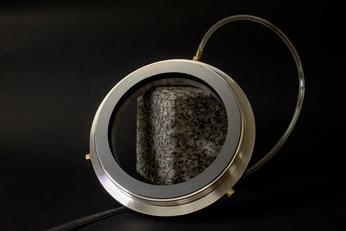 Image 5. A mechanical seal face of porous graphite that has been lapped flat.