Over-tightening, excessive speed and improper installation can cause a system to falter.
Garlock Sealing Technologies

In many respects, troubleshooting and failure analysis of packing materials is similar to the investigation of a crime scene. A good investigator knows how to gather clues from many different sources and put them together to understand what has happened. A good troubleshooter uses the same information gathering method, familiarizing themselves with the sealing materials, the process equipment and the systems where they are used.

Start by Interviewing Witnesses

The troubleshooter should seek information from the people who work with the equipment on a regular basis. Seal installers, maintenance personnel, operators, process engineers and others can all shed light on potential causes of failure. Some key questions should be:

  • How is failure defined? Some examples include excessive leakage, overheating, high rate of flush water consumption, excessive friction load and blowout.
  • Is this application the source of chronic seal failures, or was this an unexpected event?
  • Were there any changes to the seal material, the equipment or the overall process that preceded the failure?
  • Were there any system upsets or cleaning cycles that preceded the failure?
  • Can you describe the installation procedure?

Gather Information About the Victim

Knowing the limitations of the sealing product is a key step. The acronym “STAMPS” will help remember the key elements to ensure the right packing is selected for the application.

  • S: Size. Is the correct packing cross-section being used? Are the rings cut or formed to the correct length?
  • T: Temperature. Check the system temperature against the packing manufacturer’s established temperature ratings for the product.
  • A: Application. Some packings are made specifically for rotary equipment while others are intended for valves or static seals. Check to make sure the packing is suitable for the equipment where it is being used.
  • M: Media. This refers to the fluid being sealed. Check with the manufacturer or with compatibility charts to be sure the seal material is compatible with the media. If the media is slurry, abrasion-resistant materials may need to be specified. If the media is toxic, explosive or required to be contained within certain maximum allowable leakage requirements, then a packing must also be selected on the basis of its ability to seal at low leakage levels.
  • P: Pressure. Check the system pressure against the packing manufacturer’s established pressure ratings for the product.
  • S: Speed. Check the equipment speed against the packing manufacturer’s established surface speed ratings for the product. Surface speed is expressed in feet per minute or meters per second and not revolutions per minute.

Investigate the Crime Scene

When possible, observe the equipment while it is running. Can you see, hear, feel, smell or use a sensor to make observations? Smoke, vibration, grinding noises, the scent of burning fibers and system pressure fluctuations are only a few of the clues that can be noticed or measured while the equipment is up and running.

Examine the condition of the equipment. Most packings are robust seals that can handle less than perfect equipment condition, but there are limits to the amount of degradation they can withstand.

Valve stems and pump shafts or sleeves should be checked for scratches, corrosion pitting and general surface roughness. Rough surfaces can damage the sealing surface and result in excessive leakage and quick wear of
the seal.

Extrusion of the seal material
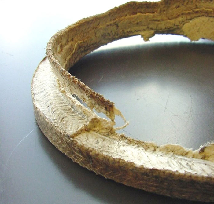
Image 1. Extrusion of the seal material (Images courtesy of the author)

Excessive clearances at the top or bottom of the stuffing box can lead to extrusion of the seal material and intrusion of large solid particle into the seal area (see Image 1). In severe cases, excessive clearance may result in a seal blowout.

Most packings are not meant to function as both a seal and a bearing. In rotating equipment, poor bearing condition may result in shaft runout that “wallows out” the inside diameter of the seal. Misalignment may result in shaft/stuffing box offset that causes one side of the packing set to be heavily compressed while the other side is compressed much more lightly. A similar side loading of a packing set can occur in large horizontally oriented valves where the packing is forced to bear the weight of the stem.

Check to make sure all the parts are in place. During the breakdown, repair and reassembly of equipment it is possible to misplace parts. Equipment might be put back into service without seat rings, bushings, lantern rings, O-rings and other parts that are essential to proper equipment operation.

Look at the seal and the equipment as a part of a big picture.

Consider how this piece of equipment is affected by other equipment and control devices in the system. For example, is there a downstream valve that creates pressure spikes in an upstream pump seal when the valve closes and the pump is still operating?

Perform Forensic Analysis

Contrary to the belief that “dead men tell no tales,” the examination of expired packing can tell a great deal about the cause of failure and the action that may need to be taken to correct the problem.

Ideally, the whole packing set should be removed, and the pieces should be arranged in the same order they were taken out. The set can then be reconstructed outside of the stuffing box and examined for clues. If the entire set of packing cannot be retrieved, then pieces or photos of the remains may still prove helpful.

Examine Common Causes of Failure

The lineup below gives some of the most common causes of packing failure. By looking at the failed packing, recognize some of the telltale signs that are left by these common modes of failure. Once they are detected, action can be taken to make sure their threat is reduced or eliminated.

Extrusion of the seal material
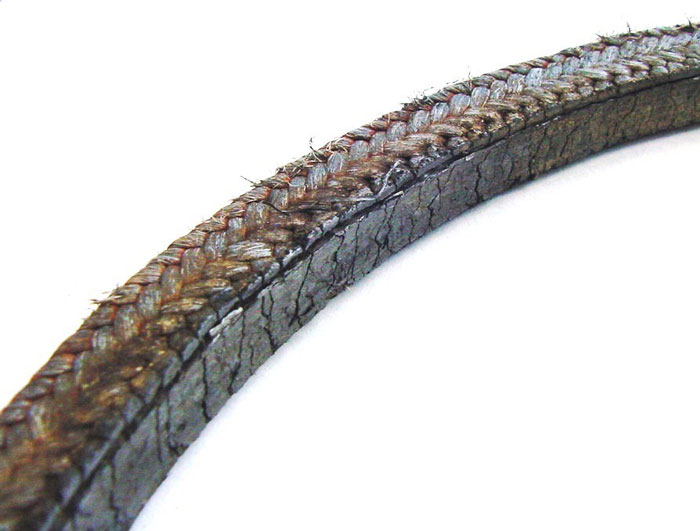
Image 2. Charred packing

Over-tightening. This is the most common cause of packing failure in rotating equipment. An over-tightened packing can be identified by a charred or melted inside diameter surface (see Image 2). The severity of the charring or melting is greatest on the ring nearest the gland follower and it decreases with rings deeper in the stuffing box. Note that most braided packings are intended to operate with a small amount of leakage that will flow out to the atmosphere along the inside diameter of the seal. This leakage cools and lubricates the surface where frictional heat is being generated. If leakage is totally cut off by over-tightening, then frictional heat can quickly rise out of control.

When making adjustments to a packed pump, remember the following principle: Make adjustments that are proportional to the leakage rate. If the pump is emitting heavy leakage, large adjustments can be made until the leakage is reduced to a light, steady stream. At this point, further adjustments should be small, and the packing should be allowed to run for several minutes before the next adjustment is made. The full effect of a tightening adjustment may not be seen for several minutes.

Excessive speed. A packing material that has been exposed to shaft speeds beyond its limit may have an appearance similar to that of an over-tightened packing, except that the charring or melting may be uniform throughout the depth of the packing set. For high speed applications, it is important to use packing materials that can withstand the higher temperatures generated by friction. Thermally conductive materials also help to dissipate frictional heat.

Extrusion of the seal material
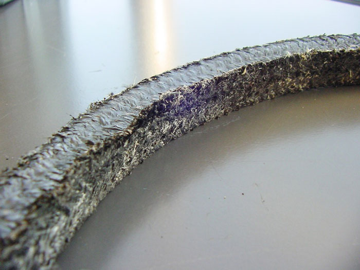
Image 3. Abraded packing

Abrasive wear. Abrasive wear of packing is recognized by the loss of material on the inside diameter of the packing set (see Image 3). While the top, bottom and outside diameter surfaces of the set may look new and in good condition, the inside diameter is worn away. Abrasive wear is usually a result of solid particles in the media working their way into the stuffing box with leakage. The use of a flushing fluid will help to push back abrasive particles into the process and keep the seal area clean. Another method for limiting the intrusion of solids into the sealing area is to use a close-fitting bushing or gasket spacer to reduce the clearance in the bottom of the stuffing box.

Abrasion resistant fibers such as Aramids can be used when exposure to abrasion is unavoidable.
If a flushing fluid is being used but abrasive wear of the packing is still occurring, then several things should be checked to make sure that the flush is operating properly.

Check for proper alignment of the lantern ring with the flush port (see Image 4). Measure the depth at which the flush port enters the inside of the stuffing box. Measure the axial length of the lantern ring. Then, calculate the number of packing rings that should be inserted below the lantern ring in order to ensure proper alignment.

Stuffing box 
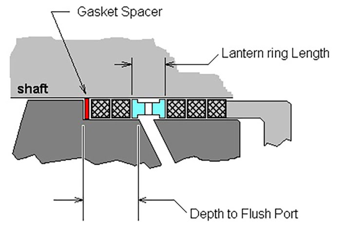
Image 4. Stuffing box and lantern ring alignment

Introduce the flush at an appropriate pressure. A flushing fluid should be introduced at a minimum of 15 pounds per square inch (psi) above the pressure seen at the bottom of the stuffing box. This will ensure that the flush flows in the right direction, carrying solid particles back into the process and protecting the seal.

If the pressure of the pumped fluid exceeds the flush inlet pressure, there is a chance that the media can back up into the flush port. If enough solids are carried back into the flush port, it can become plugged.

The flushing fluid (usually water) should be clean. Dirty flush water can damage the packing since the dirt is being injected directly into the middle of the packing set.

Excessive heat. In valve applications, the most direct source of heat is from the fluid being sealed. However, some valves may be soaked in heat from the surrounding environment. Pumps, mixers and other high-speed rotary equipment generate frictional heat between the rotating shaft and the static seal.

Chemical attack. Synthetic and vegetable fiber packings can be chemically attacked by fluids at either end of the pH spectrum. Strong acids and bases may cause damage ranging from weakening of the fibers to complete disintegration of the packing material.

If the packing is made from several different ingredients, a strong acid or base may selectively attack some ingredients while leaving others untouched. Strong solvents may also attack certain synthetic fibers, or they may dissolve and wash out grease or oil lubricants. Over time, this may result in a dry packing that does not seal well even under high compressive loading. Strong oxidizers will attack most packing materials with the exception of polytetrafluoroethylene (PTFE). The problem of chemical attack is usually solved by changing to a more resistant seal material.

Improper installation. Signs of improper installation can usually be seen upon examination of the failed packing set. Packing should be cut and installed as individual rings with cut ends that meet after they are twisted around the stem. It should not be installed as a continuous length that is “spiraled” into the stuffing box.

Packing rings that have bulges in the axial direction are indicative of rings that are either cut too short or too long. This creates gaps or overlaps at each ring and an uneven surface for each successive packing ring and an associated uneven loading of the packing.

Each ring should be installed and seated into the bottom of the stuffing box before the next ring is installed. If rings are not seated properly, this can result in heavy compression of the rings at the top of the set, while the rings deeper in the box are compressed very little. In this case, the packing may be sensitive and hard to control with adjustments.

The gland follower should be adjusted evenly so that the packing is not compressed more on one side than the other. This will also help to prevent “cocking” of the gland follower and the possibility of metal-to-metal contact with the rotating shaft.

Because the design concept behind a compression packing seal is very simple, one might think that determining the root cause of failure mode might be equally as simple for this type of product. Unfortunately, this is not the case.

Gathering information from others, learning about the seal application, observing the equipment, examining failed seals and becoming familiar with common modes of failure are all tools that can be effective in determining modes of failure and developing corrective action for improved performance.

Next Month: Elastomers in Mechanical Seals

We invite your suggestions for article topics as well as questions on sealing issues so we can better respond to the needs of the industry. Please direct your suggestions and questions to sealingsensequestions@fluidsealing.com.

Read more Sealing Sense articles by clicking here