

Pump vibration is measured by measuring the oscillatory motion on either a stationary part like the bearing housing or the rotating shaft. The units can be displacement, velocity or acceleration, and if the frequency of the vibration is known, each unit can be converted from one to the other.
Image 1 shows oscillatory vibration amplitude versus time for a single frequency, and the frequency of this vibration can be calculated by dividing the number of oscillations per unit time. In this example, there are five oscillations (cycles or revolutions) in one second or five cycles per second (5 Hertz [Hz]).
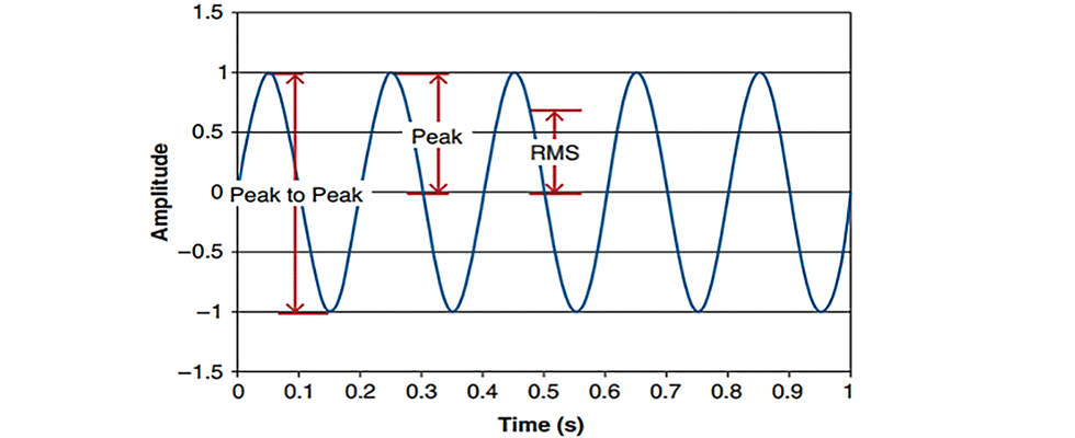
In Image 1, you will note that it is generic, and there are no amplitude units listed. As noted, the amplitude units can be acceleration, velocity or displacement. Acceleration is measured by an accelerometer and is more sensitive to higher frequency signals.
Velocity, which is the most common unit used in industrial applications, is typically calculated from accelerometer measurements and provides good sensitivity at high and low frequencies. Displacement is often measured using noncontact proximity probes to determine the shaft movement but is also calculated from accelerometer or velometer measurements on stationary components of lower speed pumps of less than 600 rotations per minute (rpm).
All of these measurement instruments (accelerometer, velometer and proximity probe) are powered by an analyzer or other means, and they provide a voltage back to the analyzer that is proportional to the vibration. The analyzer records the raw signal as a function of time (Image 1) and can also present the vibration amplitudes as a function of frequency.
Additionally, Image 1 shows that the amplitude of vibration can be represented in peak-to-peak, peak or root mean square (RMS) units. This is an important distinction as the peak-to-peak, peak and the RMS values result in different amplitudes. Peak-to-peak measurements are often used when measuring displacement and when we want to determine if the shaft is moving more than the bearing clearance.
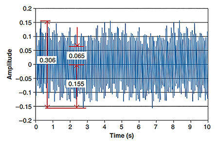
Peak is a common unit of amplitude that results in half the peak-to-peak value for a sine wave. RMS is a measure of the average velocity or acceleration. For a pure sine wave, RMS is equal to 0.707 times the peak. For the more complex waveforms (Image 2), it takes each point in the waveform, squares it, adds them all together, takes the arithmetic mean and then takes the square root of that number. In a simpler way, it is the average energy in the waveform over time.
It should be noted that RMS velocity is the standard acceptance testing unit per ANSI/HI 9.6.4 Rotodynamic Pumps for Vibration Measurement and Allowable Values when measuring the bearing housing vibration for pumps operating above 600 rpm.
For more information on vibration measurements, refer to ANSI/HI 9.6.4 and ANSI/HI 9.6.5 Rotodynamic Pumps Guideline for Condition Monitoring at pumps.org.
