

As an engineer, there are times when calculations need to be done quickly, even when all of the desired inputs are not readily available, to determine the best solution. With centrifugal pumps, these calculations typically deal with calculating a pump’s total head to select the optimally sized pump required. While referencing the existing pump and how it works would be the easiest, there are scenarios where a user cannot access that data. Here are solutions for those on-the-fly situations, as well as the best assumptions to make to accurately estimate the total head of a system.
Calculating Pump Total Head
To select a right-sized centrifugal pump, a design or pump sales engineer needs to know the desired flow rate and total head. While flow rate is relatively intuitive (or customer-driven), determining pump total head can be more challenging and lead to serious issues if calculated incorrectly.
For example, if too many safety factors are integrated into the calculation, the result can be an oversized and more expensive pump. Alternatively, if not enough are considered, the risk is an undersized pump that cannot handle the work. One result of miscalculating the pump total head is incorrect sizing of the motor and related electrical components. Other consequences can include:
- too much or too little flow
- the pump running out of the best efficiency point (BEP) and the preferred operating range (POR)
- cavitation
- vibration
- bearing issues
Basics Total Head Calculations
Centrifugal pump manufacturers commonly present performance curves with units of pump head shown in feet of liquid. An ideal pump with a given impeller diameter and operating speed will raise a liquid to a certain elevation in the discharge pipe, regardless of the density (or specific gravity) of the fluid. By using feet of liquid as the unit of pressure, the fluid’s density is eliminated as a variable.
The Hydraulic Institute (HI) defines head as the expression of the energy content of a liquid in reference to an arbitrary height, or datum—typically the pump centerline. Further, HI defines total dynamic head (TDH) as the measure of energy imparted to the liquid by the pump. More specifically, TDH is the difference between discharge head and suction head as measured between the inlet and outlet of the pump, including the energy required to overcome static elevation, friction and other losses.
When calculating TDH, the energy available at the entrance of the pump is being compared to the energy needed at the discharge to produce the desired flow, and the pump is then selected to add the additional energy required at the discharge most efficiently. This is the head routinely specified for pumping applications.
Calculating Centrifugal Pump TDH for a Water-Like Fluid
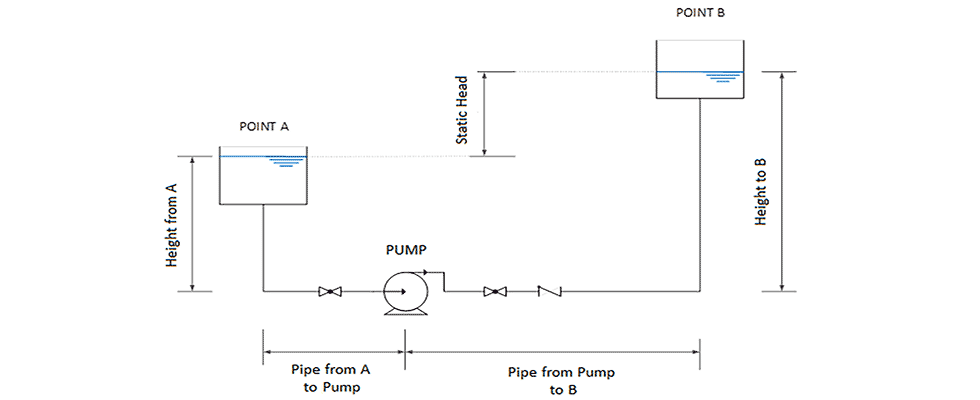
Image 1 shows an example system in which water (or a similar low-viscosity fluid) must be transferred from Tank A (suction) to Tank B (discharge). In this example, both tanks are open to the atmosphere and the water level in these tanks is kept constant. The datum is the centerline of the pump.
To quickly estimate the required TDH, despite the presence of other nuances, focus on the two primary components that are going to affect the TDH in Image 1 of the centrifugal pump system:
- the static head, or height difference, between the liquid level in Tank A and the liquid level in Tank B
- the friction head, or the pressure losses caused by the flow of liquid through the pipe and fittings, between Tank A and Tank B.
In the example, the velocity head will balance out to zero, as centrifugal pumps provide pulsation-free flow. The example tanks are also both open to atmosphere, so there is no additional pressure head to consider as well. When calculating the TDH for a water-like fluid, these and other additional components are not required and a basic calculation is shown in Equation 1.
Net static head, or the elevation difference between the surfaces of A and B, should be easy to estimate in most cases. However, if these are variable over time, start with the largest possible difference. Also, note the impact of suction lift versus flooded suction applications. In applications where the fluid source is below the pump (suction lift), the suction elevation is presented as a negative number—such that static discharge minus static suction (net static) is additive.
Equation 1: pump TDH = (±) net static head + friction head
The friction head calculation for the pipe and fittings between A and B requires a more detailed characterization of the piping system, including:
- How long is the pipe?
- What is the pipe diameter?
- What is the pipe material and how old is it?
- How many fittings and accessories are between A and B? (The number and type of elbows, tees, valves, reducers are typically required to determine the friction losses.)
- What is estimated, or target flow rate, of liquid through the pipe?
There are multiple reference sources that describe the calculations to derive a reasonable friction head value. There are also many websites offering handy online calculators to calculate the friction loss with some simple inputs about the system.
For a fast, manual estimate of a simple system, one recommended method is the equivalent length method, which considers friction loss of various fittings as an equivalent length of straight pipe. Using commonly published tables, determine the equivalent length of fittings, then add those lengths to the estimated actual length of pipe at each diameter. From there, total friction head can be determined using friction loss per 100 feet of pipe data.
Safety factors discussed earlier include pipe roughness, laminar versus turbulent flow (especially in high flow or small pipe diameter applications) and fluid viscosity. Their application is a judgment call in this exercise, but remember that more is not necessarily better. Typically, a safety factor between 10% and 15% is applied.
The sum of the net static head and the total friction head will give the TDH value for a given flow rate requirement.
How to Fix an Undersized or Oversized Centrifugal Pump
Despite best efforts, pumps are often found to be operating away from their optimal hydraulic rating. While these assumptions and computations will provide an approximate value of the pump total head and will provide a reasonable duty point (flow rate and total head), there are solutions available for correcting operations.
In cases where TDH was overestimated, the pump will have excess flow and will operate closer to runout conditions. Aside from getting additional flow, which is not always a bad outcome, the pump may cavitate as the net positive suction head required (NPSHr) drastically increases toward runout. In some cases, the motor may also overload if a borderline selection was taken. The options for remedy include:
- Decrease the impeller diameter.
- Decrease the pump speed with a variable frequency drive (VFD). This solution offers a short payback time, in some cases only a few months, and a VFD can simplify controls elsewhere. Some VFDs can offer pump-specific control and protection features, providing the option to also add process instrumentation for speed control (such as a pressure transmitter), without the need for an external programmable logic controller (PLC) or to calculate the pump flow without a flow meter.
- Partially close the discharge valve to throttle the pump. This is a way to artificially create additional friction losses in the piping system. For example, if the pump is cavitating, closing the discharge valve slowly will cause the pump to run back on the curve to a point where the cavitation stops. This is a quick way to check if the cavitation is corrected, and then proceed with any of the other methods to fix the situation on a more permanent basis.
In cases where TDH was underestimated, the pump will likely be unable to produce sufficient flow from A to B, as the pump will be running closer to shutoff conditions. The options for remedy include:
Increase the impeller diameter. This would likely mean higher horsepower required and, therefore, a larger motor. The larger motor may not fit on the same baseplate, or the motor starter may be too small, so these considerations must be evaluated.
Increase the pump speed with a VFD. While it is not common to run a motor over 60 hertz (Hz), VFDs and some motors are capable of doing so. However, this may still result in the need for more horsepower.
Survey the system for opportunities to reduce required head, such as a control valve that is usually at least partially closed. Substituting a VFD and control logic can be an opportunity to save energy and solve the issues of an undersized pump. A professional pump system assessment can help determine the best option.
A safety factor between 10% and 15% is useful as the result of overestimating pump head is less of a headache than underestimating. The use of VFDs provides increased flexibility as well, in addition to typical energy savings.
