
Achieving unity power factor through the use of synchronous condensers can be a win-win situation for power utilities and consumers.
07/12/2016
This article continues my previous article on power factor (Pumps & Systems, April 2016, read it here), which prompted interesting responses from readers. Specifically, we will look at this question: What is a synchronous condenser, and what does it have to do with power factor? Here is a quick review of power factor: Power factor is the factor by which apparent power, or kVA, is multiplied to obtain kW.
- kW = Power Factor x kVA
- Power Factor = Cosine of Angle = kW / kVA
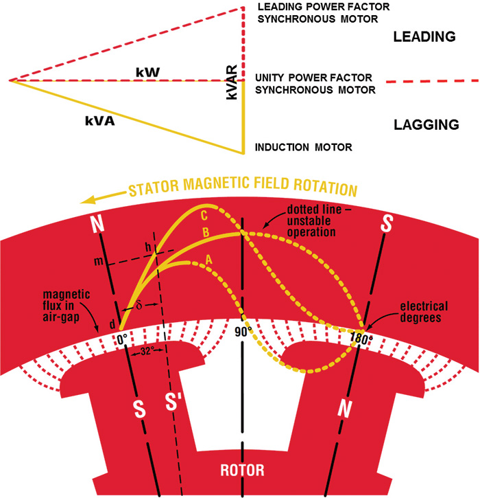 Figure 1 (top). Graphical representation of the power factor calculation. Figure 2 (bottom). A diagram showing stator magnetic field rotation (Graphics and images courtesy of the author)
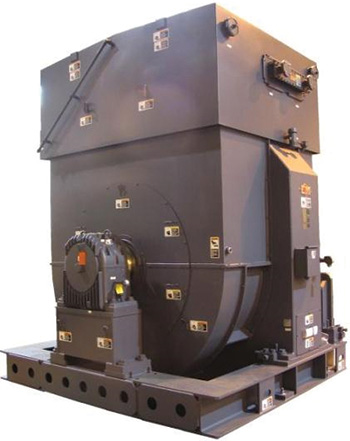 Image 1. A 7,200-horsepower, 20-pole, 4kV synchronous motor
How Does a Synchronous Motor Work?
As mentioned earlier a synchronous motor and condenser are one and the same. That being said, the diagram in Figure 2 shows conditions in a synchronous motor when operating in synchronism and at no load. When the motor is loaded, the rotor will drop back along Curve C, the curve of synchronous torque, sufficiently to develop the load torque. Curve C is the resultant of magnetic reluctance torque, Curve A, and the definite polarity torque, Curve B. The maximum synchronous torque is reached at about 70 electrical degrees lag of the rotor.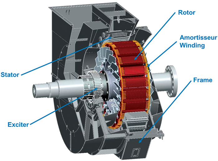 Figure 3. The main components of a synchronous motor include the frame, stator, rotor, exciter and amortisseur winding.
Synchronous Motor as a Condenser
An overexcited synchronous motor (condenser) has a leading power factor. Increasing the condenser’s field excitation results in furnishing reactive power (vars) to the system. In an industrial plant with a large number of induction motors, synchronous motors (condensers) can be used to supply some of the reactive power required by induction motors. This improves the plant’s power factor and reduces the reactive current required from the grid. The main advantage of a synchronous motor (condenser) is the ease with which the amount of correction can be adjusted. Unlike a static capacitor bank, the amount of reactive power from a synchronous condenser can be continuously adjusted. Reactive power from a static capacitor bank decreases when grid voltage decreases, while a synchronous condenser can increase reactive current as voltage decreases. Another benefit of synchronous condensers is their ability to control voltage levels. A synchronous condenser naturally supplies more reactive power to a low voltage and absorbs more reactive power from a high voltage, plus the field can be controlled as previously mentioned. The reactive power improves voltage regulation in situations such as starting large motors or in systems where power must travel long distances from where it is generated to where it is used.Conclusion
The power generators would like their customers to present a load to the power grid as close to unity power factor as possible. Unfortunately, this is not happening given the number of induction machines. However, the utility is required to provide peak voltage and current in the wave form at any given time.
A power factor of less than 1 results in an increased cost to the power generator. Many utilities are passing this cost to their customers in the form of power factor correction charges. Therefore, achieving unity power factor through the use of synchronous condensers can be a win-win situation for both the power utility and the consumer.
To read more Motors & Drives articles, go here.
To read more Motors & Drives articles, go here.
