

Power and electricity are an essential part of modern life and important to the world’s economy. Global energy trends show demand for smart technological solutions which must provide the highest possible reliability and withstand all upcoming hazards. The strict requirements of the standards applied in these industries must be followed to ensure safe operation. The modern economic paradigm also dictates a need to maximize operational efficiency.
Rotating equipment, and industrial pumps in particular, is the most critical equipment in terms of both reliability and efficiency. Proper selection of an industrial pump is important for the whole process. Modern industrial pumps must also ensure high efficiency within various operation regimes where not only head and capacity are changing, but also fluid data such as specific gravity and viscosity. Pump regulation is commonly used to fulfill this requirement.
This article describes different ways of pump regulation with its highlights and shows total cost of ownership for various applications. In this article, users will learn how speed regulation and application of a fluid coupling in particular helps increase reliability and efficiency of the whole operational process.
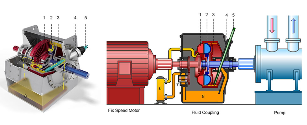
1 - pump wheel, 2 - turbine wheel, 3 - shell, 4 - scoop tube housing, 5 - scoop tube, 6 - oil cooler,
7 - oil pump, 8 - oil tank
Different Methods of Pump Control
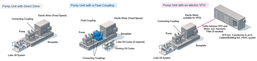
Image 1 shows three main methods of pump control: throttling, usage of a fluid coupling and an electric variable frequency drive (VFD).
In the case of throttle control, the pump is driven directly by means of a fixed speed electric motor being rigidly connected to the pump via a coupling (usually spacer type). Control of pump head and capacity is then done via a throttle valve installed on the pump’s discharge line. A high level of wear in the throttle valve and a huge drop down in efficiency makes this control method limited in application and is usually used if only a narrow control range is required.
Both methods, via a fluid coupling or a VFD, use speed control. In the case of a VFD application, the pump and the motor (typically coupled via a spacer type coupling) are rotating at the same speed given by the VFD. In the fluid coupling option, a standard fixed speed motor is used, and the speed control is done via the fluid coupling. So, VFD and fluid coupling applications require different motors. In the case of VFD control, a motor must be equipped with an insulated bearing as well as VFD-suitable motors with a higher service factor compared to the fixed speed motors. This may lead to a bigger motor frame size and additional related costs. Application of a fluid coupling allows using a standard fixed speed motor, which is an additional benefit in terms of price and reliability.
The fluid coupling concept uses the principle of torque transmission by means of fluid circulation between two impellers. The mechanical energy from the driver is converted into kinetic energy through the pump wheel, hence into energy of the fluid flow (oil), and from there it is again converted back to mechanical energy in the turbine wheel. The speed of the turbine wheel can be changed by changing the amount of circulating oil (using a scooped pipe or scoop tube, such machines are called fluid couplings), or by using adjustable vanes (such machines are called torque converters).
Since there is no direct metal contact between the driver and the driven machine (oil acts as the medium that transmits the torque), wear is not typical for this type of torque transmission.
The design and main components of the fluid coupling are shown in Image 2. The oil flow circulates through the oil cooler by means of an oil pump, which is driven by the driver’s shaft via a gear. The oil flow is fed to the pump wheel, which is rigidly coupled to the drive shaft, where it is accelerated and discharged to the turbine wheel, which is rigidly coupled to the shaft of the driven machine (pump).
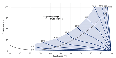
Changing the position of the scoop tube changes the amount of oil contributing to the power transmission process. The resulting consequence: more oil in the fluid coupling increases the output speed to the pump or, vice versa. There is always a minimum slip of around 2% that remains to transmit energy between the pump wheel and the turbine wheel. Image 3 shows how the coupling performs along the characteristic curve according to the scoop tube position. The typical speed control range by means of fluid coupling 20% to 98% of the motor speed.
Another feature of a fluid coupling is its ability to work also as a lube oil system, which is required if the pump and/or motor operates with sleeve bearings. Therefore, a separate lube oil system is not required.
Closing the general overview with the VFD option, it should be noted that there is talk of sophisticated technology with a lot of components adding substantial complexity to project layouts. A typical 4 megawatt (MW) 6 kilovolt (kV) VFD consists of a transformer section, a couple of power grids sections, a control section and requires quite a lot of space compared with a fluid coupling: approximately 6,000 millimeter (mm) width, 1,500 mm depth and 3,000 mm height.
Comparing Economic Criteria of Different Control Methods
In this article, the following example and comparison of three main economic criteria are considered: capital expenditure (capex), energy savings and maintenance costs. The application is as follows:
- boiler feed water pump on a combined cycle power plant
- network voltage: 6 kV
- motor rated power: 4 MW
- four operating points: pumps run eight months per year on the nominal point (pump head of 2,030 meters [m] and capacity of 580 cubic meters [m3/h]) and four months per year on other three points (reduced speed: 95%, 90% and 85% of the nominal pump speed)
- pump and motor use sleeve bearings
- energy price of 0.10 euro per kilowatt per hour (kWh) and annual inflation of 1.5%
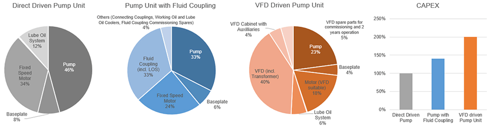
Split of capex for all the three control options are shown on Image 4 where the following is noted:
Direct driven pump unit requires a throttle discharge valve which is a part of the hydraulic system and is not considered in the current study; however, this should also be noted by designing the whole hydraulic system.
Pumps are the same for all three pump units: a pump for a fluid coupling option could have a large impeller diameter to compensate fluid coupling’s slip. Usually, it is just a different impeller trim which is not causing change in cost.
Direct drive and fluid coupling options use a fixed speed motor while a VFD option uses a special motor suitable for VFD (with an isolated bearing). Cost increase for this special motor execution is usually +5% to the fixed speed motor price.
Direct drive and VFD driven pump units use the same baseplate; the baseplate for a fluid coupling option is usually a bit longer since a fluid coupling is installed directly on the baseplate between the pump and the motor. However, if a lube oil system is required and should be installed on the baseplate, the footprint for all the three options is almost equal.
Fluid coupling option requires two connecting couplings per unit while direct drive and VFD option require only one per unit; however, connection couplings cost is almost neglectable for all three options.
VFD cost itself is more expensive compared to fluid coupling’s cost; VFDs also require cabinets with auxiliaries (HVAC system); depending on the project a separate proper clean room could be required—this could lead to construction costs which were not considered within the current study but must be observed on the power plant design phase.
Total capex for the pump unit with fluid couplings is 41% higher compared to direct driven pump unit; VFD driven pump unit is twice as expensive in capex compared to the direct driven pump unit.
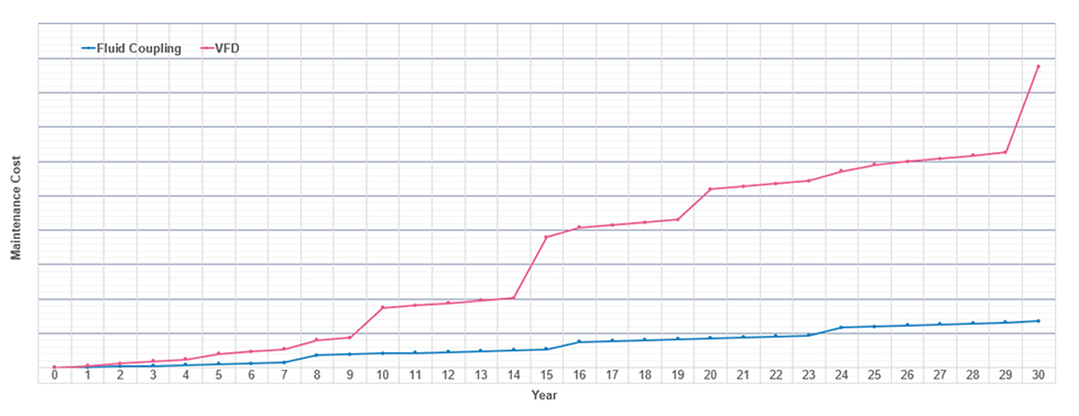
Considering throttle valve reliability and maintenance cost for both speed regulations options, the fluid coupling is a mechanical piece of equipment. This is a centrifugal machine working on oil, which requires little annual maintenance. Major overhaul is usually once per eight years. A VFD on the other hand, usually requires more spare parts and works on an annual basis. Also, major overhauls over a lifetime are more frequently executed. Image 5 shows maintenance cost dynamics for 30 years for both variable speed drives (VSDs): fluid coupling and VFD. Data is based on market expertise and operator feedback.
The pump runs eight months per year at the rated point and the other four months on reduced capacity. Image 6 shows pump curves for these operating points and related pump power consumption.
Interaction of a system curve (S1, S2, S3, S4) and pump head-capacity (H-Q) curves are causing pump operating points. Operating point 1 is the nominal pump operating point where the pump works most of the time. The pump H-Q curve here is rated for the nominal motor speed which is equal to the pump speed in case of direct drive. In the case of usage of a fluid coupling, pump speed is equal to the fluid coupling output shaft speed which is a bit lower than motor speed due to slip in a fluid coupling.
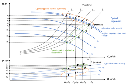
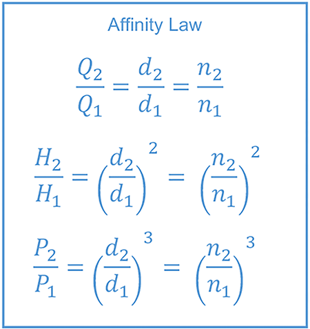
To maintain the same head and capacity values, pump manufacturers use different impeller trim (larger diameter) which usually does not cause any change in price. So, the pump still works in operating point 1 for all three control options as nominal. By means of closing the throttle valve on the pump’s discharge line, hydraulic system curves are getting steeper and points 2, 3 and 4 are reached. In the case of speed control, the pump curve moves down based on affinity laws and the operating points 2, 3 and 4 are reached. Affinity laws also allow to draw the pump consumed power curves. Since the pump’s consumed power is changing to the power of three of pump’s speed, it shows that all the operating points reached by speed control require less power compared to throttling.
Image 7 shows energy savings over throttling. This chart takes into consideration the operating scenario, analyzes consumed power and efficiency of the motor and details fluid coupling over VFD—including integrated transformer and its auxiliary equipment. Both options allow savings over throttle control in a 30-year lifetime.
Summarizing all three main economic aspects (capex, maintenance cost and energy savings), it shows that both speed control methods not only provide required operational modes but also save money.
Many installations worldwide and years of operation confirm fluid coupling is a reliable, robust and cost-effective solution when it comes to pump control—not only for power market, but also for many applications in the oil and gas industry.
Further development of geared VSDs uses a planetary gear and the principle of separate power transmission. Such a drive consists of a torque converter and a planetary gear, which are both installed in the same housing. Approximately 75% of the power is transmitted via a planetary gear, and the remaining 25% is transmitted via a torque converter. Changing the position of the guide vanes (shown in green) adjusts the planet carriers’ speed and direction of rotation and thus the sun gear speed is regulated. The sun gear is rigidly connected to the output shaft which rotates the driven machine.
There are different ways to regulate the pump speed; the choice of each is determined by specific tasks and operating conditions of each individual project. The reliability and durability, as well as high efficiency of fluid couplings and geared VSDs, make them a good solution for regulating industrial pumps.
