

With the constant rise in equipment costs, building owners and engineers are looking for ways to decrease initial and utility costs for heating, ventilation and air conditioning (HVAC) projects. This has driven the market standard to pumps with variable speed drives and high efficiency condensing boilers.
These condensing boilers can be divided into two subcategories based on the volume of water they can hold and leads installers to consider choosing high mass fire-tube boilers versus low mass water-tube boilers.
Choosing a Boiler System
There are several factors to consider when determining which type of boiler system is optimal for the given application.
When thinking of the needs of the system, users should compare the differences in the chart below to validate they are choosing the right kind of system.
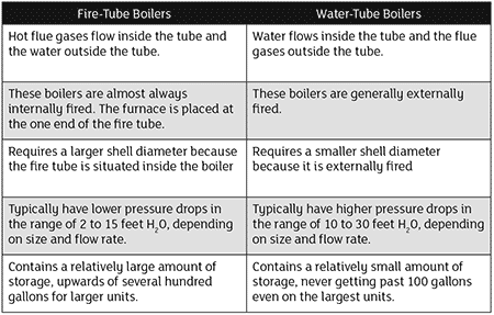
Comparing Fire-Tube Boilers to Water-Tube Boilers
One notable difference between these two boilers that has affected the design of systems is that higher mass boilers do not need to maintain a constant flow. Fire-tube boilers can handle a wide range of capacity through them.
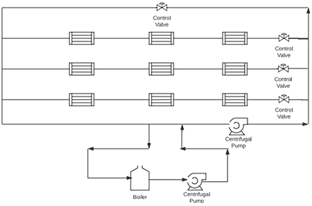
By using just one set of variable speed pumps to serve the boilers and terminal units, a variable primary system has been created.
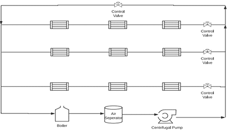
Variable primary systems have provided an alternative to the traditional primary and secondary design, which is still required for water-tube condensing boilers and other boilers with a low mass design.
With a variable primary flow design, the need for a second set of pumps within the boiler loop is eliminated, which can reduce the initial cost of the system. One popular topic of conversation regarding these large mass boilers, when they are designed in a variable primary system, is the boiler’s minimum flow rate and how it affects the system.
The Boiler’s Minimum Flow Rate
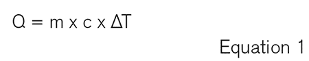
One formula users will need to understand for this topic is a heat transfer formula that is used quite often in HVAC (Equation 1).
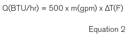
Considering that HVAC projects in the United States usually measure water flow in gallons per minute (gpm) and not pounds per hour (lb/h), and that the c value of water at 60 F is around 1.0, the formula (Equation 2) is often simplified to read:
When relating Equation 3 to a boiler, translate it as:
How Low Can the Flow Water Be Through the Boiler?
Some important information that is needed to solve this equation is the minimum capacity of the boiler. If this is not given, it can be calculated using the turndown of the boiler and its maximum capacity.
The final piece of information needed is the temperature rise. Usually this will be designed by a mechanical engineer and is typically set somewhere in between 20 F and 60 F.
To find the minimum flow rate possible through the boiler, consult the boiler’s manual and look up the highest temperature rise allowed per the manufacturer. This rise is normally 80 F or 100 F. All boilers have a maximum temperature rise. If the inlet and outlet temperatures are any wider, it will create enough thermal stress on the heat exchanger to break it.
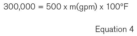
As an example, let’s say there is a 3 million British Thermal Unit per hour (BTU/hr) boiler that is capable of a 10:1 turndown. That means the minimum output is 300,000 BTU/hr.
If the boiler manufacturer states that the maximum temperature rise of the boiler is 100 F, users would use the following equation (Equation 4):
Solving for the flow rate, the minimum flow is 6 gpm. If the flow is any lower, the boiler will shut itself off in order to protect it from damage.
All boilers have a minimum flow rate at which the boiler can continuously fire even if it is implicitly stated.
Taking a look at the operations manuals for several major manufacturers of fire-tube boilers; they all have a relatively similar sequence of operations. They all use a system supply temp sensor and follow the (simplified) order of operations below:
- When there is a call for heat, the boiler will turn on at low fire.
- If the set point is not reached, the boiler will increase its firing rate.
- If the set point is exceeded, then the boiler will decrease its firing rate.
- If the set point is exceeded at the minimum firing rate, then the boiler will shut off.
Using the boiler from the previous example and a system design temperature rise of 40 F, the heat transfer formula looks like Equation 5:
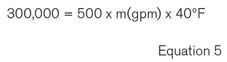
This gives a minimum system flow rate of 15 gpm. Any less than this and the boiler will surpass its set point and shut off until the supply temperature drops again.
It is important to limit the number of times the boiler will cycle on and off in a given period of time. The more often the boiler cycles, the more frequently the boiler will need to be serviced. Frequent cycling of the boiler will also lead to an increase in energy consumption due to the loss of the thermal energy stored in the heat exchanger and vent being lost to the outside. If a building is going to have frequent periods of low heat demands compared to its design point, a good solution would be to have several smaller boilers to increase the boiler plants turndown.
While any fire-tube condensing boiler can handle little to zero flows through the heat exchanger while the unit is not firing, no boiler can sustainably continue to fire when flow through the boiler is less than its inherent minimum running flow.
In order to properly size a boiler plant, the designer needs to look at the full range of heat loads that will be required for the building and be aware of the limitations of the equipment they are selecting.
The System Dictates the Choice
In a hydronic system, both fire-tube and water-tube boilers can be viable solutions. A water-tube boiler can be a good selection on a retrofit job with limited space for a large boiler. A primary secondary setup is easy to integrate with an existing system.
A fire-tube can also be a good solution for a system with only one set of variable speed pumps. They have the ability to handle varying flows through their heat exchangers without risk of damage.
It is still important to keep in mind that even fire-tube boilers have limits in terms of flow variance. Every building is unique, and likewise, the best boiler plant solution will depend on the system the user is viewing.
