

In the author's August 2020 article, the methods of trimming an impeller and underfiling the discharge vanes to gain head were discussed. In this presentation, the effects of speed change on net positive suction head (NPSH) and filing the impeller suction vanes to gain NPSH will be addressed. In addition, the combination of underfiling and overfilling the discharge vanes to address vane pass vibrations will be discussed.
Changes in NPSH due to Speed Change
Changes in speed will affect NPSH. The approximate new NPSH value can be obtained by the formulas below. Unlike head and capacity, a change in diameter has little effect on NPSH. For speed change up to 20%, NPSH can be calculated by the following formula.
NPSH1 = NPSH2 * (N1/N2)2
If the speed changes by more than 20%, the formula is expressed as follows:
NPSH1 = NPSH2 * (N1/N2)1.5
Note that the formula does not produce exact results. If the NPSH margin is critical, caution should be observed to assure adequate NPSH results.
Overfiling Suction Vanes to Gain NPSH
Underfiling of the suction vanes is useful for decreasing the NPSH required (NPSHr) in smaller impellers. A typical underfile would decrease the thickness of the suction vanes to about 1/16-inch and bullet-nose (elliptical profile) the leading edge. This applies to impellers up to about 13 inches in diameter. For larger impellers, the thickness should be increased proportionally. Note that the larger the impeller, the fewer results will be obtained because the vane thickness is a smaller percentage of area than the impeller eye opening.
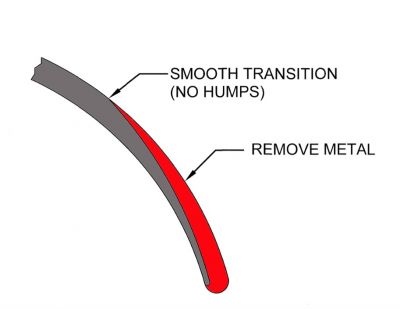
Reducing the vane thickness opens the area of the suction passage allowing the velocity to decrease at a given flow rate. Through the formula for conservation of energy, this increases the head. The typical decrease in NPSHr is one-half to one percent. The overfiling must be blended as far back into the impeller eye as possible with no sudden change (humps) in the vane profile. In extreme cases, the suction vanes can be filed to a near-knife edge to maximize NPSH performance.
To further increase the area of the suction passage between vanes, the vanes can be cut back to gain more area and NPSH. This increases the area and produces more pressure to reduce cavitation. Caution should be observed in cutting back the suction vanes as the hydraulic performance may be degraded. Typical for a 10-inch impeller would be .38 to 0.5-inch. More for larger impellers, less for smaller ones.
For achieving the best possible NPSH performance, the impeller eye should be polished and the vanes evened up so that they are all performing the same. It is important that the vane spacing is equal and the vanes are true to the center of rotation.
When addressing NPSH, the impeller should be chucked in a lathe and centered in respect to the shaft. This is best done by mounting the impeller on a mandrel. True up the suction eye by making a minimal cut to assure that the passage is running true, then polishing the passage and vanes to a 63 or better finish. This polishing should be extended into the vanes as far as possible.
The vane tip is filed to about 1/16-inch thick and blended back as far as practical into the existing hydraulics. It is important that there is a smooth transition into the existing hydraulic contour. For impellers more than 12 inches in diameter, this thickness should be increased in proportion to the impeller diameter.
Alteration for Vane Pass Vibration Reduction
Vane passing vibration is common with pumps at or near full diameter. Sometimes this is excessive and must be addressed to prevent mechanical failure. Besides seal and bearing failure, it is common to see breakage of piping connected to the pump or even failure of the impeller shroud. For pumps handling petroleum products, any failure of the pressure boundary is a serious problem. Not only is the cleanup expensive, but it could result in a fire that could destroy the unit and injure personnel.
Vane passing vibration is caused by the compression of the product between the vane and volute as the vane passes the nozzle. As the vane passes the volute lip, the fluid does not have enough time to move out of the way and is compressed, producing a shock wave and displacement of the impeller that is seen as vibration. By minimizing the shock wave and spreading it over a longer period of time, the impact is reduced.
Reducing the vane impact requires a way to relieve the pressure created as the vane passes the volute lip(s). Several things can be done to create a path to relieve the pressure. These include filing the impeller vanes to reduce their thickness, filing the vanes to increase their skew to spread the event over a longer time period, beveling the shroud at the discharge to help relieve the pressure pulse, grinding the volute on the impeller side to thin the nozzle lips and cutting the nozzle lips at an angle.
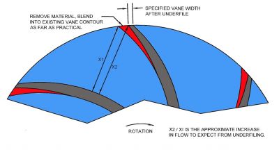
If the vibration is not excessive (one or two inches per second out of tolerance), the impellers can be underfiled to thin the blades at the discharge. The underfiling reduces the vane thickness to about 1/8-inch at the discharge and the filing is blended back as far as possible into the existing impeller hydraulics. There can be no perceivable humps in the blade or efficiency can be degraded.
In addition the distance between the impeller and volute lip can be increased. This is accompanied by thinning the volute nozzle by grinding the volute on the impeller side so that the nozzle tips are approximately 1/8-inch thick. The lips are bullet-nosed to offer a smooth transition of the flow from the volute into the nozzle. The grinding must maintain the gradual increase in area from the nozzle throughout the volute profile.
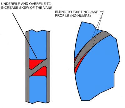
For higher vibration levels, the vane tip can be filed to increase the skew of the discharge vanes. This thins the vanes, similar to underfiling, and distributes the shock wave over a longer time period. In addition, the nozzle lips are cut at a 20-degree angle, opposite the angle of the vane. By spreading the impact over a longer period of time, the vane passing vibration is substantially reduced. Note that this procedure usually reduces the efficiency of the pump by about 1%.
For large pumps, the loss of 1% efficiency may be troublesome but considering the reduction in maintenance and downtime it should more than make up for the additional energy cost. Downtime is expensive and for pumps handling a flammable or dangerous product, a seal failure or a rupture in the seal piping could cause personal injury or leakage of the product.
In Image 3, the figures show how the impeller vanes are modified to lessen the impact of the blade passing the cutwater. In all cases, the impeller filing must be consistent between vanes and blended back into the existing hydraulics. No humps are allowed that can be felt by running a finger along the vane profile.
