Extra energy transmitted can produce larger sealing stress on the gasket.
Inertech, Inc.

The bolt as a screw is one of the six simple machines. A simple machine magnifies or changes the direction of an input force. By means of mechanical advantage, a bolt can dramatically increase its input force. Take for example an 8-bolt flange with 3/4-inch diameter bolts. By manual effort alone, a person can easily develop a total bolt load of over 110 tons. This article explains the mechanics by which the mechanical advantage is possible and then draws attention to how friction can deteriorate the end effect of a bolt’s mechanical advantage.

The means by which a bolt can greatly magnify input load is by leverage. One source of this leverage is afforded by the geometry of the bolt. The other is the leverage from a tightening tool—in this example, a torque wrench. To illustrate the mechanics of a screw thread, consider a 3/4-inch diameter, Unified Course (UNC), A193 B7 bolt with a yield strength of 105,000 pounds per square inch (psi). Image 2 identifies the geometrical characteristics of a bolt that create leverage.

image 1 threads of a bolt
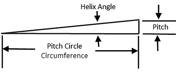
Image 1. The threads of a bolt essentially form an inclined plane (Images courtesy of Inertech, Inc.)

The pitch circle is defined as the circle that passes through the pitch line of the threads. The pitch line is the theoretical point of contact between the male and female threads. The pitch is the distance between thread crests, and is the axial distance the bolt travels in a single 360-degree turn. The threads of a bolt essentially form an inclined plane wrapped around the minor diameter of the bolt (Image 1).

The horizontal distance (pitch circle) traveled divided by the vertical distance traveled (pitch) is the mechanical advantage of the bolt geometry.

For the 3/4-inch bolt, the values for the pitch (P), pitch circle diameter (Pd) and pitch circle circumference (Pcc) take on the following values: 0.10 inch, 0.6850 inch and 2.152 inch, respectively. The helix angle becomes Tan-1 (P/Pcc) = 0.266 degrees. The pure mechanical advantage of the threads, designated as MAt, is the horizontal distance traveled divided by the vertical distance traveled, in Image 2. Its value becomes MAt = 2.152 inch/0.10 inch = 21.52:1. Relative to the pitch circle, 1 pound of input force would create almost 22 pounds of output force.

image 2 geometrical characteristics
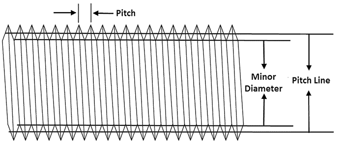
Image 2. The geometrical characteristics of a bolt that creates leverage

Now evaluate the additional mechanical advantage of a torque wrench. Presume the use of a 3/4-inch drive, 48-inch-long torque wrench with an effective length (based on the pull-point of a person’s hand) of 44 inches. The mechanical advantage of the wrench is its effective length (Le) divided by radius of the pitch circle.

Now calculate the pure mechanical advantage of the wrench (MAw) as Mw= Le/(Pd/2) = 44 inches/(0.6850/2) = 128:1. A single pound of input force on the torque wrench results in 128 pounds of output force.

To get the total pure mechanical advantage of this system, combine MAt and MAw. This is done by taking the product of the two values.

The total pure mechanical advantage (Mtot) of the two effects then becomes Mtot = Mt x Mw = 21.5 x 128 = 2,752:1. If the mechanical advantage actually attained this value, 15 pounds of input force would yield the bolt.

Obviously, it does not. The reason is, pure mechanical advantage of a system can never be attained. There are always (energy) losses.

In the instance of a bolt being torque tightened, those losses can be extraordinarily high. The most important energy loss is friction. To better understand how dramatically friction can negatively impact a bolt’s clamping force, evaluate its affect using a common, long-form version of the torque equation. Tlbf is the calculated torque to attain a bolt load, FB.

The first term in Equation 1 is the useful input energy that goes to stretching the bolt. The second and third terms account for the energy being lost to friction.


T = [(pt/2 π) + (utdt/2 cos(a)) + (un dn/2)] FB/12
Where:
pt = pitch of the bolt thread = 0.10 inch
dt = mean contact diameter of thread = 0.685 inch
dn = mean contact diameter on nut spot face = 0.8738 inch
a = half thread angle = 30 degrees
ut = friction coefficient on threads = 0.13
un = friction coefficient on bearing surface (spot face) = 0.08
FB = value of (single) bolt load = 17,561 lbf.
T = torque, in. lbf.
Equation 1


Specifically, the second term is the energy lost to friction between mating threads, while the third term accounts for the energy lost to bearing surfaces during the tightening process. Now evaluate these terms for the example bolt.

In addition to bolting geometry values, consider the published values of friction coefficients for a commonly used paste, lubricant. The definition and values for each variable are noted in Equation 1.

Substituting these into the respective terms they are evaluated and compared in Image 3. Term 1 is the useful work in creating the clamping force.

image 3 input energyImage 3. Input energy going into stretching the bolt (Term 1), and energy lost to friction (Terms 2 and 3)

The sum of the other two terms is the energy loss to friction.

In this particular instance, with the presumed coefficients of friction, only ~16 percent of the applied energy is converted to the useful work of creating bolt stretch. A total of 84 percent of the tightening load is lost to friction. This explains why only a small portion of the system’s mechanical advantage is realized. The effect of friction should not be underestimated. A torque wrench measures the value of torque being input to the bolt system. It does not reveal how much useful energy is actually being delivered to the bolt.

Clearly, the proper use of lubrication can have a dramatic effect on the success of a bolted flange connection. The liberal use of lubrication is one of the easiest, least expensive, quickest and most effective ways to ensure the targeted clamping load is realized. In the case of gasketed, bolted flange joints, the extra energy transmitted produces a larger sealing stress on the gasket and ultimately results in few emissions and a cleaner, safer environment.

We invite your suggestions for article topics as well as questions on sealing issues so we can better respond to the needs of the industry. Please direct your suggestions and questions to sealingsensequestions@fluidsealing.com.

Read more Sealing Sense articles by clicking here.