

Improvements in variable frequency drive (VFD) technology have resulted in lower costs, improved reliability and increased use. Most modern VFD systems have internal diagnostics that create automatic shutdown on faults. However, the cause of these faults can sometimes be elusive to locate and correct. However, de-energized and energized motor testing can provide valuable insight to help identify many of these problems. This article highlights how to incorporate these motor testing techniques into VFD troubleshooting.
Basic Operation
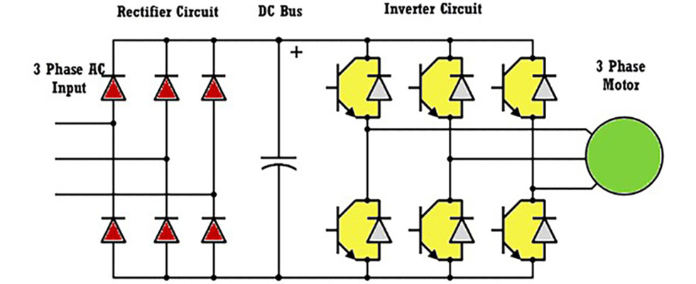
A VFD rectifies the incoming three-phase, alternating current (AC) power to create a direct current (DC) bus. The DC bus uses capacitors to smooth the rectified DC as input to the invertor section. In the invertor section, the controller uses microprocessors to control semiconductor switches that convert the DC voltage to a variable three-phase AC voltage and frequency input to the motor.
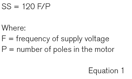 By controlling the amount of time the semiconductors (silicon-controlled rectifier [SCR] or insulated-gate bipolar transistor [IGBT]) are firing, the width of the DC pulses modulate the DC to produce a simulated three-phase input voltage with variable voltage and frequency. The frequency of the input voltage determines the speed at which the magnetic field rotates around the stator. The speed at which the magnetic field is referred to as the synchronous speed (SS).
Due to the switching nature from the invertor circuit, VFDs can create power quality (PQ) issues by introducing harmonics into the plant’s electrical system. Additionally, VFDs can also be sensitive to incoming PQ issues, causing them to shut down. Many VFDs have internal electronics that indicate the cause of the shutdown. These common codes assign the cause of the overvoltage, over current, overload, voltage, current unbalance, over temperature or external faults. This information is important, but the real question is: What caused the fault condition? Is the fault condition caused by the VFD or experienced by the VFD?
If the fault is experienced by the VFD, it could be the result of incoming power, connections issues, any one of many motors issues or faults in the driven machine or the process itself. If the fault is caused by the VFD, it could be the result of the breaking down or failed electronic components. Among the common failures are diodes in the rectifier section, capacitors’ on the DC bus or breakdown or failure of a semiconductor in the invertor section.
De-Energized Motor Testing
Motor circuit analysis (MCA) is a motor testing technique that injects a series of low voltage AC and DC signals through the motor windings to thoroughly evaluate the entire motor system while the motor is de-energized. MCA motor tests can be performed directly at the motor or remotely from the output of the VFD. Unlike traditional de-energized motor tests that fail to identify rotor problems or developing winding insulation breakdown, MCA tests provide early indication of developing faults in the ground wall insulation system and the insulation surrounding conductors used to create the coils in the stator as well as existing or developing faults in the electrical portion of the rotors.
MCA can identify faults in the earliest stages but can also quickly confirm the motor is “good,” which can eliminate the motor as the cause of the VFD trip. By performing the three-minute test from output of the VFD, a “good” result not only indicates the motor is in good condition but also that all the associated cabling and electrical components in the tested circuit are in good condition as well.
However, if the results indicate “bad,” an additional three-minute test directly at the motor is performed. If the motor tests “well,” this means the test was conducted properly and the fault is in the cabling or controller. If the motor indicates a developing fault, there are optional MCA tests available to determine if the fault is in the rotor or the stator electrical circuit.
The low-voltage DC tests provide indication of connection issues in the circuit under test to confirm all of the external and internal connections are sufficiently tight. The series of AC tests exercise the winding insulation and identify the small changes that occur in the chemical makeup of the winding insulation as the insulation between conductors begins to degrade.
The optional dynamic test requires manual rotation of the motor shaft under test and develops a stator signature that identifies any developing faults in the insulation surrounding the conductors in the coils making up the stator winding system. The rotor signatures identify faults in the rotor electrical system such as static or dynamic eccentricity, cracks, breaks or casting voids in the rotor bars or end rings.
Energized Motor Testing: Electrical Signature Analysis
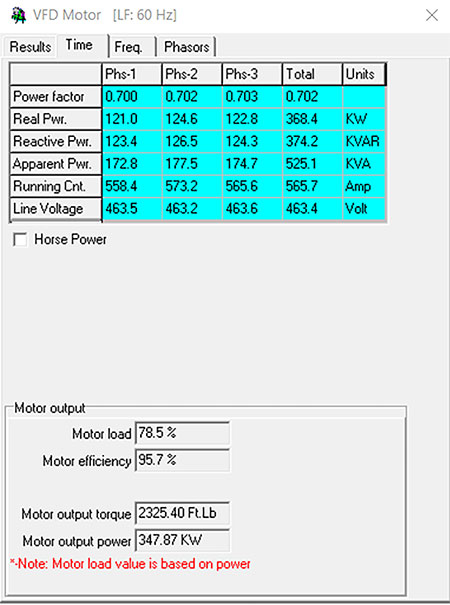
Electrical signature analysis (ESA) uses the VFD’s input and output voltage and current to quickly analyze the condition and quality of power being supplied to the drive as well as the voltage and current output from the drive to the motor. Each of these tests requires less than a minute. Performing ESA motor tests on the input and output of the drive provides a complete profile of input and output power.
Each test performs a simultaneous data capture of all three phases of voltage and current to create PQ tables for each of the three phases, captures and displays and stores 50 milliseconds (msec) of the voltage and current waveforms for all three phases. Additionally, 50 seconds of the voltage and current waveforms are digitized and used to perform high and low frequency fast Fourier transforms (FFTs) on both the input and output voltage and currents.
Input Power
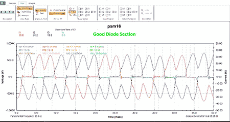
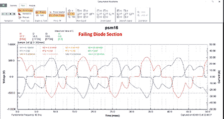
The input voltage to the drive provides valuable information indicating the condition of the incoming voltage supplied to the drive. It calculates any voltage, current unbalance or harmonic content in the incoming voltage or current. The input current indicates the diode’s condition in the rectifier section of the drive. Image 2 shows the current waveform with all diodes firing properly. In Image 3, it can be quickly determined that one or more of the diodes are not firing properly.
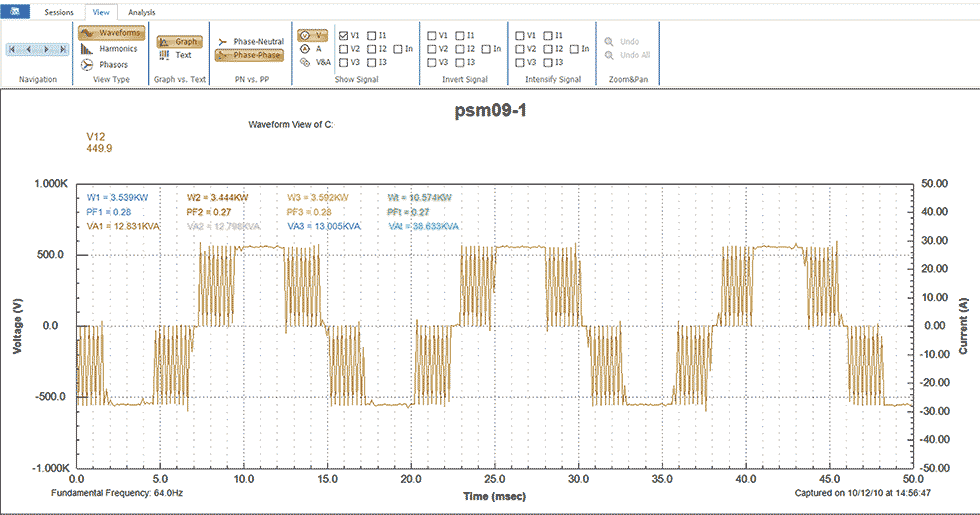
Output Voltage
The output voltage from the drive provides information about the condition of the drive itself as well as the quality of the power being provided to the motor. This is including, but not limited to, the proper or improper operation of the semiconductors in the invertor circuits and developing failure of the DC bus capacitors. Image 4 provides a snapshot of one phase of the voltage output of the drive, which is the input voltage to the motor.
All of the output voltage waveforms should be relatively uniform and symmetrical. Nonsymmetrical voltage waveforms indicate failing or failed IGBTs. Ripples on the flat portion of the positive and negative portions of the waveforms iare an indication of failing capacitors on the DC bus. A failed $20 capacitor can destroy an entire drive.
Output Current
The motor’s current acts as a sensitive transducer for the motor system. Any existing or developing faults in the motor, the driven machine or the process itself will cause the motor’s current to modulate. These modulations in the output current indicate the electrical or mechanical condition or any anomalies in the process itself. An FFT on the digitized voltage and current waveforms identifies faults in the motor such as cracked or broken rotor bars, static or dynamic eccentricity.
Early indication of developing rolling element bearing failures, balance and the alignment condition of the rotating components of the motor or the driven machine can also be quickly identified using the same fault frequencies long recognized in vibration analysis.
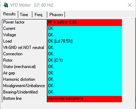
Automatic Analysis
The ESA software combines all the information gathered in the 50-second data acquisition process and compares them to predetermined standards, guidelines and algorithms to create the graphs, tables and displays required to evaluate the condition of the entire motor system from the incoming power to the process. On completion of the evaluation, ESA creates a complete, detailed report that not only highlights developing problems in the electrical portion, developing faults in the driven machine or other equipment connected to the motor but also anomalies in the process that could cause the VFD to trip. The report produced also details measurements that are within predetermined guidelines, thereby eliminating most of the guesswork normally associated with VFD troubleshooting.
By incorporating MCA and ESA into the VFD standard troubleshooting process, the analyst has the most detailed information available to quickly determine if the fault is caused by the VFD or experienced by the VFD. The three-minute MCA identifies bad motors and can eliminate the motor as the cause of the failure and ensure that if a new motor is being installed, it is fault-free. ESA confirms power into and out of the VFD is fault-free in a test that takes less than 1 minute.
