

Equation 1
Efficiency is the ratio of output and input power expressed as a percent (Equation 1). Pumping systems are no different, but sometimes the terms used to describe efficiency change and can be confusing to someone who is not well-versed. Commonly, you may hear the terms pump efficiency, bowl efficiency, volumetric efficiency, overall efficiency, wire-to-water efficiency, system efficiency or some other term. Interpreting these terms and what they mean requires a review of fundamentals.
A simple pumping system is provided in Image 1 (top of page). In this system, there is a supply tank that is open to atmospheric pressure (0 pounds per square inch gauge [psig]), with a 5-foot (ft) level and 5-ft elevation above grade. These values represent the potential energy forcing liquid into the pump. Next, there is a head loss (HL) term representing the friction losses in the inlet piping and valves. Moving through the system, there is a pump adding energy to the system and other components (piping, valves, process component, control valve and a product tank) in the system consuming the energy, resulting in a system energy balance. The system energy balance means the system head at a specific flow rate will equal the pump total head at that flow rate.
Using the system in Image 1, we can start defining different efficiency terms but to do that we need to define how power is calculated. The starting point is to calculate the power required by the system or what is defined as pump output power (Pw) shown in Equation 2:
Pump output power is sometimes referred to as hydraulic power or liquid/water power. The terms used in Equation 2 are flow rate in gallons per minute (Q), pump total head in feet (H), specific gravity (s) and a conversion constant for U.S. units to result in horsepower (hp). Specific gravity refers to the ratio of the liquid density to the density of water at standard temperature. In this example, water is at ambient temperature so the specific gravity will be 1.0. Using the flow and head for the supply pump in Image 1, the calculations show the pump output power to be 54.6 horsepower (hp) and in Equation 3, the pump efficiency (η) is calculated to be 55.9% by dividing by the 98.02-hp pump input power (P) listed in Image 1.
Equation 3
The pump efficiency calculation is specific to the bare pump (Image 2) and does not include the driver or other drive train components. A similar efficiency term used with vertically suspended pumps is bowl efficiency. These pumps typically have a series of impeller/diffuser bowls that are connected to the surface by a column pipe (Image 3). The column pipe length and number of line shaft bearings will vary depending on the depth of the well. For this reason, the head loss in the column pipe is not considered in the bowl assembly head and other mechanical power losses may be excluded in the bowl efficiency.
.jpg)
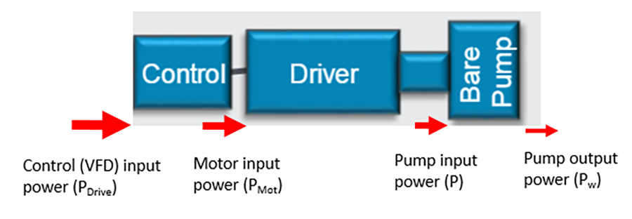
Image 2 includes the driver and control as additional components. In this example, the control is a variable frequency drive (VFD). The red arrows go from larger to smaller from left to right, which represents an efficiency loss in each component that is added to the system. Considering the power into the VFD in Image 2, the overall efficiency (ηOA) can be calculated as shown in Equation 4:
Another term used to describe this is “wire-to-water” efficiency—meaning that it is considering the electrical input power. The drive input power includes the individual component efficiency of the driver and VFD in this example. If it is assumed that the driver (motor) efficiency is 95% and the VFD efficiency is 97%, the input power to the VFD and the overall efficiency can be calculated as shown in Equations 5 and 6.
Equation 5
Equation 6
Another term commonly used is “system efficiency.” It should be noted that system efficiency is not defined within Hydraulic Institute standards, and when it is used, it typically is not clear if the person is referring to the pump and drive train efficiencies (i.e. overall efficiency) or a more theoretically calculated efficiency that considers the piping system that the liquid is flowing through. If used to relate to unnecessary head loss within the piping system, then the “optimal” system hydraulic power consumption would need to be defined (i.e. minimum flow rate and head to achieve the system requirement). There is no standard method to define this; so, look at the concept in simplistic terms with several assumptions. In Image 1, there is a head loss across a control valve of 46.57 feet. Assuming this is the only unnecessary head loss in the system and 1,300 gallons per minute (gpm) is the minimum required system flow, then the hydraulic power loss across the valve could be calculated using Equation 2 and subtracted from the pump output power (Pw). A system efficiency could also be calculated assuming the flow remains constant at a lower head and other component efficiencies in the pump drive train are constant.
To illustrate this concept, the supply pump with driver and VFD operating at full speed (106.4 hp) is operating with the control valve head loss of 46.57 feet. Assume the pump speed is then reduced so the system operates with the valve fully open to achieve the 1,300 gpm, and the efficiency of the pump, motor and VFD remain constant. For this simplified example, the power loss across the valve is described in Equation 7, and the system efficiency is calculated as 37% in Equation 8 compared to 51.3% overall efficiency in Equation 6.
Equation 7
Equation 8
The point of this example (and the many assumptions) is to illustrate that efficiencies can be gained by reducing losses in the piping system. As illustrated, it is always a good idea to look for losses in the piping system and determine if there is a way to eliminate them while meeting the system requirements. However, the concept of system efficiency beyond the pump and drive components is something that depends on many dependent variables and is not precisely defined. Therefore, it is best to compare the power consumption for different options and calculate the energy consumption for the expected operating points and duration.
