

Pumps and compressors are frequently characterized by complex geometries, motion and physical phenomena—such as cavitation, pressure pulsation and vibration, all of which affect the efficiency and reliability of the device.
Taking these factors into account is critical to designing an optimal machine, and computational fluid dynamics (CFD) is a tool that can streamline the process. CFD predicts fluid behavior in a given system and can help users optimize design at a reduced cost compared to building a prototype and taking experimental measurements.
What Is CFD?
CFD is a numerical method for solving and analyzing problems involving fluid flow. The typical workflow for setting up a CFD simulation starts with a CAD model of the geometry. The simulation domain is then divided into discrete computational cells, called a mesh.
The properties of the mesh—the size, shape and location of the cells—will determine the solution accuracy.
Thus, setting up the mesh properly is paramount for obtaining useful results. Meshing has traditionally been performed manually by the CFD engineer, but the process can be laborious and take days or even weeks, especially for applications with moving geometries like pumps and compressors. Today, advanced CFD codes offer automated mesh generation, which eliminates this time-consuming step and uses algorithms to create a mesh that is optimized for the particular case.
Once the mesh has been created, relevant physical models for fluid motion, turbulence, heat transfer, etc., are selected and boundary conditions are defined. During the simulation, the governing equations are solved iteratively at each time-step. Certain CFD codes offer features that adapt the computational mesh throughout the simulation to add cells when and where users need them to capture complex physical phenomena.
The results of the simulation can then be viewed and analyzed with post-processing software.
Why Use CFD?
CFD allows engineers to “see” inside a pump or compressor during operation, which provides valuable insight into the physical processes taking place. CFD often incorporates a multi-physics approach, enabling users to analyze important phenomena such as fluid-structure interaction, cavitation and thermal expansion. It is critical to understand the interaction between the fluid motion and the motion of valves and other
moving components in the pump or compressor. Fluid-structure interaction modeling allows users to accurately simulate the real-world interplay between the fluid and solid components.
gerotor pump
Cavitation is another important phenomenon to analyze, as it can severely damage the machine. Multi-phase modeling captures the interaction and transition between liquid and vapor phases, allowing users to predict the onset of cavitation and to determine how to modify the design to avoid it.
For machines like screw compressors, one can use heat transfer modeling to analyze the effect of thermal expansion on gap size. The knowledge gained through CFD can be used to improve pump/compressor design.
In addition to studying specific phenomena, CFD simulations provide virtual measurements that allow users to analyze the overall performance of the pump or compressor at any point before building a costly physical prototype. Not only does this save time and money, but users can also test more designs. With automatic mesh generation, setting up simulations for various geometries is trivial, and the result of the process is a reduced time-to-solution.
Some CFD packages offer tools specifically for design optimization studies. For example, genetic algorithm optimization is a technique that invokes a survival-of-the-fittest approach to efficiently optimize a design. These tools can accelerate the process.
Overall, incorporating CFD into the development workflow offers an advantage in a competitive market by allowing users to create a better product and bring that product to market faster.
CFD methodologies have been validated for many types of pumps and compressors. Here are two examples: a gerotor pump and a scroll compressor.
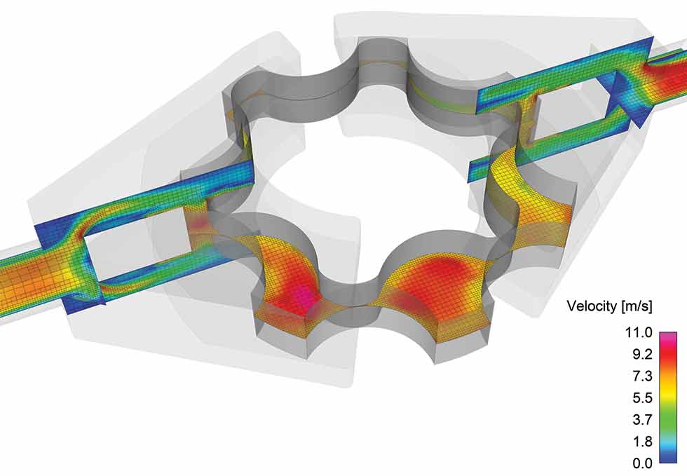
Gerotor Pump
Commonly used in hydraulic motors, gerotor pumps are made up of eccentric geared rotors, one internal and one external, within a housing. The rotors form sealed chambers that change in volume and shape as the fluid is pumped, and it is important to maintain as small a clearance as possible to minimize leakage losses at the sealing lines.
To design effective gerotor pumps, a user must accurately model sealing, and there are several CFD methods to accomplish this. One option is to block the seals entirely, which will speed up the simulation, but this approach does not capture the leakage flows that occur in the physical system.
One could alternately choose to resolve the flow in the gaps by adding a sufficient density of cells. This option is accurate, but it requires more time and computational resources. Another method is to use a gap model, which requires fewer cells within the gap and balances the computational cost and accuracy of fully resolving the leakage flow.
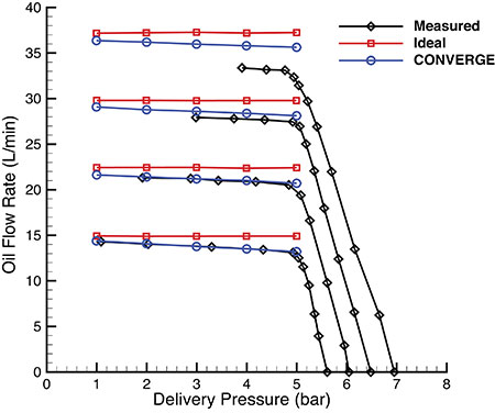
In this example, a CFD study was performed to investigate the effect of different clearance values on
the oil flow rate at varying speeds and pressures in a gerotor pump.
Image 2 shows the results for a specific clearance value, and each line represents a different speed. At a certain point, the effects of cavitation cause the measured oil flow rate values to drop. The purpose of this particular study was not to predict cavitation, and thus the simulated results stop at 5 bar.
Note, however, that CFD can predict cavitation with the appropriate model.
In this study, the CFD results (blue circles) shown in Image 2 generally agree well with the measured values (black lines).
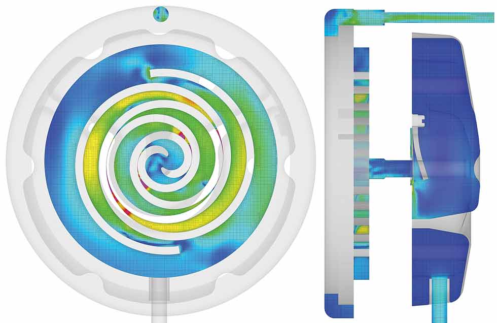
Scroll Compressor
Reducing noise and improving efficiency are two of the main design focuses for scroll compressors, which are commonly used in refrigeration applications.
It is important to investigate how modifying the geometry influences the compressor efficiency and pulsation level. The geometry of scroll compressors is complicated, and moreover, a CFD model must account for valve dynamics.
To simulate moving geometries such as that of the scroll compressor, some CFD codes rely on a mesh that moves with the geometry. Moving meshes, however, can introduce numerical viscosity artifacts that lower the accuracy of results.
In this example, a stationary mesh with a modified cut-cell strategy is used. Stationary meshes have high accuracy and stability and do not introduce numerical diffusion related to grid motion. Additionally, the cut-cell method perfectly represents the underlying geometry and allows for boundary motion while conserving mass, momentum, energy and species.
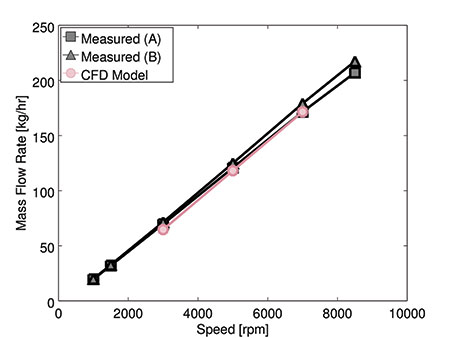
Image 4 shows the results of the global mass flow rate—a crucial parameter in determining the compressor’s cooling capacity and efficiency—for a CFD simulation of a scroll compressor.1 The CFD model is in good agreement with the measured data.
High-fidelity, three-dimensional CFD studies are valuable for designing and optimizing pumps and compressors. In the past, running CFD simulations required specialized training and long wait times for results.
Nowadays, CFD software packages include graphical user interfaces that walk users through the process of setting up a simulation with minimal training necessary. Additionally, improved hardware and the introduction of high-performance computing have reduced simulation runtimes, providing quick turnaround for design studies.
References
1. Rowinski, D., Pham, H.-D., and Brandt, T., “Modeling a Scroll Compressor Using a Cartesian Cut-Cell Based CFD Methodology With Automatic Adaptive Meshing,” 24th International Compressor Engineering Conference at Purdue, 1252, West Lafayette, IN, United States, Jul 9–12, 2018.
