

High energy pumps that operate in arduous conditions need to be manufactured using the best possible materials to ensure long-term reliability. For applications that involve seawater and produced water, super duplex stainless steel is commonly specified as the main manufacturing material due to its corrosion resistance.
However, the high cost of this material can become a major factor when designing larger components and operators can request alternatives to be assessed for their projects.
At the same time, pumping applications can change and the equipment involved needs to be upgraded to match the new requirements. For legacy pumps, this can create several challenges as operators need to establish the most cost-effective way to deliver the new specifications. Elevated pressures may rule out super duplex as the most suitable material, a situation that can be resolved by inconel weld overlay.
Material Characterization
Super duplex is a material commonly used to create pump casings for seawater, produced water and certain oil and gas applications. It provides the required corrosion resistance in correlation with the fluid that the pump is required to handle.
This metal belongs to the corrosion resistant materials that possess high pitting resistance, which is calculated by a weighted average of key elements, such as chromium, molybdenum and nitrogen, using Equation 1.
Equation 1
PREN = %Cr + 3.3 x
(%Mo + 0.5%W) + 16 x %N
This calculates the value known as the pitting resistance equivalent number (PREN), which represents the material’s ability to resist localized corrosion in the form of pitting. For the applications mentioned above, the PREN should be greater than 40.
However, while the chemical composition of super duplex offers high strength, a wide range of corrosion resistance and moderate weldability, it does have some limitations. The metallurgy of duplex stainless steels is more complex than for ferritic or austenitic steels, which means they are more difficult to produce and to fabricate. This impacts material costs.
In addition, duplex steels can form several unwanted intermetallic phases, like sigma and alpha prime, if the material is not given the correct processing, especially in heat treatment. Super duplex steels are especially prone to embrittlement and reduced corrosion resistance when the cooling rate during manufacture or welding is not high enough. This can narrow the range of applications that are suited to these materials.
High Pressure Solutions
Finally, applications that involve elevated pressures require greater wall thickness, which is especially relevant for pump casings. However, super duplex materials are only qualified to a certain extent for this purpose, so in high pressure situations, manufacturers and those involved in repairing or retrofitting pumps need to review their options.
The topic of welded pump casings came to the fore once again with the increasing pressure requirements for the pumps. In 2011, another study gained similar insights into the previous investigation. As operating pressures up to 10,000 pounds per square inch (psi) (690 bar) were called for in some applications, super duplex was less preferred than the option with a welded casing design, leading to the successor projects of the prototype.
At this level of fluid pressure the pump casing needs to be thicker, but this went beyond the wall thickness for which the forged super duplex material was qualified. At the same time, the costs for the machining preparation of the weld and the welding itself, including the weld qualification, can sometimes be offset by the higher market price for super duplex.
Developing Alternatives
One possible alternative is to use a carbon or low alloy steel for the casing and to weld all process-wetted surfaces with a corrosion resistant overlay, such as Inconel 625. The decision to use this process to clad the casings with this nickel-based material depends on current raw material prices and on the size and weight limitations of large super duplex parts.
A low alloy material with 2.25% chromium and 1% molybdenum content has become an accepted base material in the industry for parts that are welded with Inconel 625. It was also selected, as it offers similar material strength as super duplex if the appropriate heat treatment is applied.
The weld overlay method is usually best suited where super duplex is not the most appropriate material selection due to the limitation relating to the heat treatment process. Efficient and effective quenching during the heat treatment is challenging for thicker super duplex components; there is a risk of embrittlement and reduced corrosion resistance. Super duplex is therefore not qualified for thicker parts with a limitation for wall thickness at approximately 250 millimeters (mm). To protect less noble materials, such as carbon steel or low alloy steel, with a corrosion resistant weld overlay, it becomes a valuable alternative.
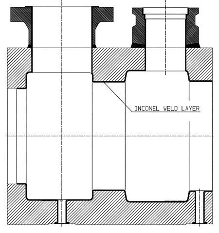
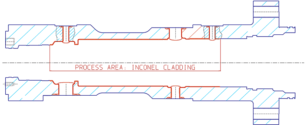
In 2008, a fluid engineering company developed its first pump design that employed this weld overlay process. One area that had been clad with Inconel was the process wetted contour inside of the pump casings (Image 1). This prototype enabled a comprehensive investigation into the feasibility of using pump components that included weld overlays.
Technically, a wide range of carbon or low alloy steels can be used as the base material, significantly reducing the cost of the components. Part of the investigation was to elaborate on the different candidates for the base material of the casings and on the design of the casing profile that needs to be protected by the weld overlay. These investigations were accompanied by cost considerations, which would affect the viability of the process in the long term.
Welding Processes & Technical Process Requirements
In general terms, a weld overlay project consists of three steps. First, the base material is machined to create the space to accommodate the weld overlay. A specialist welder is then used to apply the higher specification metal, such as Inconel 625, before the component is returned to the machine shop for final dimensioning.
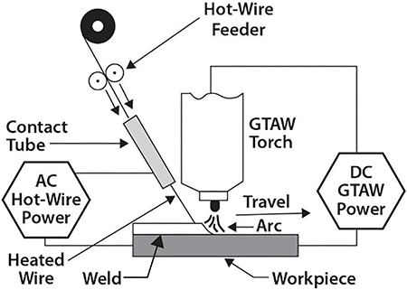
The development of the weld overlay procedures involved a mechanized gas tungsten arc welding (GTAW) process, which was used in the projects that followed the first welding trials.
The welding setup contains a nonconsumable tungsten electrode that generates the arc, whose heat must be sufficient to melt metals.
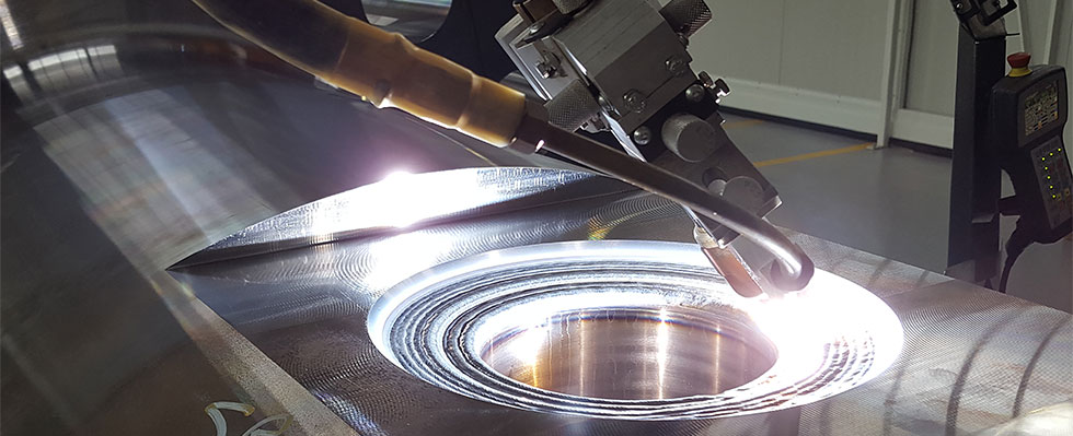
In this case, Inconel 625 is the metal that will be fused with the low alloy steel casing material. An Inconel wire is continuously fed to the weld arc and the work piece. The weld arc is protected by an inert gas shield that prevents contamination of the weld area (Image 2).
There are several challenges that arise with the welding process. However, the fluid engineering company partnered with a qualified specialist welder that was able to achieve the required high-quality welding and handle pump casings weighing several tons. Three requirements of the weld specification will be addressed.
Iron Composition
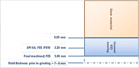
The dilution and the iron content in the weld need to be carefully controlled. Two composition classes are specified for nickel-based alloys N06625 according to American Petroleum Institute (API) 6A (International Organization for Standardization [ISO] 10423) for the chemical analyses: Fe5 and Fe10.
The abbreviations stand for the maximum allowable iron-content accumulating at the location 3.2 millimeters (mm) from the base material (Image 3). Any increase in the iron content of the weld layer beyond that specified increases the risk of corrosion.
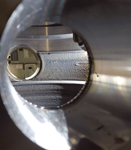
Weld Thickness
Another requirement specifies that at least two layers of welding need to be applied on the base material. The view through the casing bore (Image 4) reveals the slightly furrowed appearance of the welded layer.
Once the welding is complete, a post-weld heat treatment (PWHT) is conducted to ensure the required material properties and to release residual stresses.
In this case, the fluid engineering company decided to obtain a final machined weld thickness of 5 mm. The intention was to compensate for any deviation in terms of manufacturing tolerances and potential erosional wear that can occur during operation.
Several manufacturing steps are required to obtain the final weld geometry and it was one of the project ambitions to minimize the deviation as far as possible, in terms of the weld thickness, to reduce the time required for final machining. To target a final weld thickness of 5 mm, the machining for the weld preparation and the final machining that followed the welding needed to be designed and have its dimensional tolerances set.
Small Bores
There are further challenges when it comes to the welding of bores. Welding accessibility to casing bores is restricted by the size of the welding tool.
Smaller bores can be established with solid Inconel pipes that are welded into a pre-drilled and slightly larger opening in the casing. A further option would be to insert a solid cylinder made from Inconel into an opening. The final machining will be done afterwards by drilling a bore into this welded-in core.
Execution
Three pump units with Inconel-clad casings have been completed since the first welding tests were carried out on these types of pump components. The first design was for a subsea installation in the Gulf of Mexico. The second order was for an oil and gas project in the middle east and the third application has been related to a pump processing carbon dioxide (CO2). The projects involved welding the process area of larger pump casings (see Image 5).
The biggest pump casings measured over three meters in length. The size and weight of these components, which tip the scales at several tons, added to the complexity of the project.
Following the procedure described above, the initial forging was passed on to the machining facility, then to the welder for the cladding process and finally machined to achieve the final dimensions on the welded surfaces.
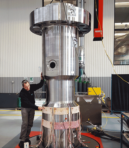
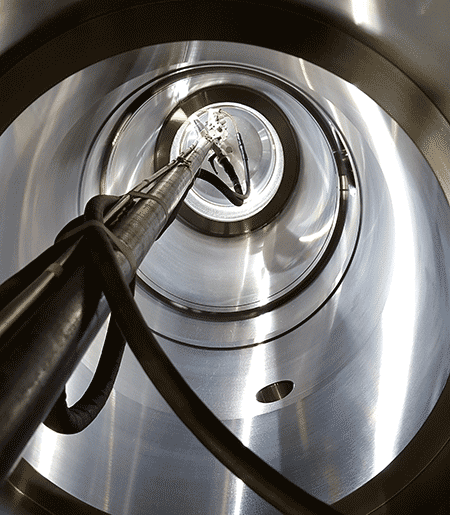
Due to the size of these pumps, the casings were positioned vertically (Images 6 and 7) for the weld cladding process, enabling the welding torch to be aligned to the required accuracy.
Two of the pumps came with a specific weld requirement related to the gasket grooves of the flanged pipe connections that are arranged outside of the pump casing. The interface on the pump casing includes machined grooves whose purpose is to accommodate the metallic gaskets.
The selection of the material for the gaskets is standardized and correlates with the filler material of the weld. Both the gasket and the weld cladding are made from Inconel 625. The project required all gasket grooves to be clad (Image 8). The purpose of the welding was to prevent galvanic corrosion between the gasket and the less noble base material, which is the pump casing described in this paper.
The use of weld overlay on pump components can be an effective alternative to the conventional selection of corrosion resistant parent materials, such as super duplex, for pumps that operate in a corrosive environment. However, a cost estimation needs to precede the final material selection as prices for super duplex and the low alloy steel can fluctuate, as does the delivery time for the individual forged raw materials.
The tendency toward higher pressure classes and, therefore, thicker pressure retaining parts, favored the material selection with the low alloy composition 2.25% chromium 1% molybdenum. The qualification of pump casings made from super duplex is limited to a certain forging thickness. As this trend continues, there will be a greater demand for weld cladding either to retrofit existing pumps or in the creation of new assets.
The fluid engineering company’s development of this process has proved successful with the manufacturing and welding procedures being fine-tuned for the pump units described. This has been achieved because the individual manufacturing steps, including forging, pre-machining, welding and final machining, have been well-aligned together in a collaboration with a specialized welding partner.
