

The increasing importance of limiting emissions draws attention to the biggest culprit for this in conventional pumps—the mechanical seal. Emissions pose a safety and environmental risk, and they also have a huge impact on maintenance costs and lost production time.
Sealless pumps do not use a mechanical seal that leaks into the atmosphere, thus eliminating the possibility of leaking fluids, dangerous or otherwise, into the environment. This category of pumps offers additional simplicity in eliminating coupling alignment, bearing frame maintenance and auxiliary systems associated with lubricating or cooling bearings.
The two main categories of sealless pumps are canned motor pumps (CMPs) and magnetic drives (or mag drives). CMPs offer increased safety through double containment, a reduced number of bearings (and inherent maintenance costs) and improved reliability when applied properly to the application.
How Is the Seal Eliminated?
Due to the laws of physics, higher-pressure fluids want to move to lower-pressure areas. Because traditional pumps must couple to a driver (motor or turbine), the shaft needs to exit the pump pressure boundary (pump case). This means the high-pressure fluid created by the rotating pump wants to leak into the atmosphere along the shaft penetration. This is stopped in traditional pumps by using gland packing or a mechanical seal.
CMPs utilize a different approach by using a common shaft for the pump and motor and containing it all in a pressure boundary. This eliminates the pressure differential across the rotating seal and the driving force for the fluid to leak. Using a common pump and motor shaft has other benefits, such as eliminating coupling alignment (both hot and cold), therefore eliminating this potential failure point in the pump.
Material Considerations
CMPs are constructed of materials compatible with most process fluids yet are not overly expensive. The typical metallurgy of wetted components of a canned motor pump are type 304 stainless steel with the stator and rotor cans made from Hastelloy C276. Although Hastelloy C, a nickel-based alloy, is more exotic and expensive compared to 300 series stainless steel, the higher electrical resistivity significantly reduces the eddy current losses in the stator can, and to a smaller degree, the rotor can. Overall, using Hastelloy results in increased efficiency of the motor.
Additionally, since the stator and rotor cans are fabricated from a thin material (0.010 inches to 0.015 inches) to minimize electrical losses and reactivity, it is important to use strong and highly corrosion-resistant materials. The cans are further supported by the electrical steel laminations along the length of the lamination pack and with heavier-duty backup sleeves at the wire coil end turn regions. These support the thin can in dealing with the high internal pressures (up to 6,000 pounds per square inch [psi]/42 megapascal [MPa]) within the motor.
For sealing of joints, there are typically face-to-face gasket designs and O-ring gaskets with a machined groove. For both types of joints used to seal the pump-to-motor and motor-to-end cover mating surfaces, it is important to verify the compatibility of the material with the process fluid. A standard design uses polytetrafluoroethylene (PTFE) gaskets due to their vast compatibility with various process fluids. For higher temperature and pressure applications (above 390 F and 580 pounds per square gauge [psig]), a spiral wound stainless steel is typically used. The grade of stainless steel will be matched to the pump case. For special chemicals or specific applications, other gaskets may be used, and the individual compatibility of those fluids with the gaskets must be assessed. If using an O-ring joint design, a Teflon-encapsulated Viton O-ring is common, as it provides the corrosion resistance of Teflon and the elastomeric resilience of Viton.
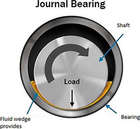
The bearing material for CMPs generally falls between two materials: carbon graphite and silicon carbide. An important point to understand with CMPs is they use fluid film bearings.
This means during operation the rotating surface of the shaft (or shaft sleeve) does not come in contact with the stationary bearing. Instead, as the shaft rotates, it creates a fluid film, and the fluid is forced between the shaft and the bearing. The typical design uses a hardened polished metallic surface on the rotor and softer corrosion-resistant bearing material. The bearing material is designed to be easily replaceable during periods of maintenance. Carbon graphite grades typically offer a softer, more forgiving bearing that is more tolerant of particulates and upset conditions but will not last as long as silicon carbide grades.
Conversely, silicon carbide being a harder material will last longer in the right application but is less tolerant of particulate wear and upset conditions. One material is not necessarily better than the other, and material selection should be based upon the application and user requirements/preferences. Other materials, such as polyether ether ketone (PEEK) and other composites, can also be used but are less common.
Considerations of Motor Fluid Properties
When considering the bearing lubricity and motor cooling, it is necessary to understand the requirements and characteristics of the canned motors as they relate to the fluid properties. Typically, the pumped fluid lubricates the bearings and cools the motor. In some instances where the pumped fluid is not compatible with the motor (too much particulate, viscosity issues, etc.), a barrier fluid can be used in the motor.
The motor fluid must have appropriate viscosity to provide adequate lubrication of the hydrodynamic bearings yet have sufficient flow through the motor to cool, all while keeping fluid friction drag losses to a minimum. Generally, fluids with an absolute viscosity greater than 200 centipoise or less than 0.07 centipoise are not desired. An alternative solution when the pumped fluid cannot be used inside the motor involves a barrier fluid. A labyrinth seal is used to isolate the pump, and the motor is filled with a compatible fluid different than the pumped fluid. In some cases an internal mechanical seal is used. This seal does not leak to the atmosphere, but instead leaks a small amount of motor fluid into the pump end. With either sealing option, it is essential to ensure the compatibility of the motor (barrier) fluid with what is being pumped.
As previously mentioned, the fluid inside the motor is used to cool the motor, along with lubricating the bearings. The fluid will therefore increase in temperature as it circulates through the motor. As the fluid temperature increases, so does the fluid vapor pressure—and typically the viscosity decreases. For these reasons, it is important to evaluate the thermodynamic properties of the motor fluid and ensure it will not vaporize or “flash” in the motor. This might cause vapor lock and/or insufficient bearing lubrication.
The temperature rise of the motor fluid is not only a function of the amount of waste heat generated by the motor’s inefficiency, but also of the specific gravity, specific heat (heat capacity) and the flow rate of the fluid through the motor. In addition, the thermal conductivity of the fluid will affect the heat transfer rate from the motor, and ultimately, the temperature rise of the motor windings. Motor winding wire has an insulation class determining the maximum temperature the wire can be exposed to. Typically, CMPs use Class H (180 C) or Class N (200 C), although other ratings are available. Note that class designations for those above Class H are typically specified in International Electrotechnical Commission (IEC) 60085.
Taking this into consideration, there are six main fluid properties of the motor fluid that are to be considered for a given application. These are:
- specific gravity
- specific heat
- viscosity
- vapor pressure
- freezing point
- thermal conductivity
As the viscosity and vapor pressure of some fluids can vary significantly with temperature, it is best practice to understand these properties at various temperatures. This would generally be at normal operating, minimum operating and maximum operating temperature. It is worth noting most manufacturers have a wealth of knowledge on various commonly pumped fluids, so they can offer support in defining these if they are unknown at the specification stage.
As the viscosity and vapor pressure properties do not vary linearly with temperature, the three points mentioned can be used to generate an approximate curve providing these values to be calculated for other temperatures.
