

In Part 1 of my column, I explained the reasons to shorten total priming time.
- Reduction in priming time mitigates the inevitable and rapid temperature rise for both the mechanical seal and priming chambers. The goal—and mantra—is to prime before you flash.
- The pump should be located as close as possible to the suction source to reduce the overall volume of the suction system.
- The suction pipe should be the same diameter as the pump suction. Note that in some cases it will need to be one size larger to reduce friction factors.
- For the purpose of friction reduction, in addition to overall pipe length, other system elements—such as elbows, valves, strainers and foot valves—should be minimized.
- To prevent air and noncondensable gases getting trapped in a system high point, the suction pipe must have a continuous rise from the liquid surface level to the pump.
- To mitigate air entrainment issues (vortex induction), ensure the suction line is sufficiently submerged. Calculate critical submergence for the worst case.
Priming Methods
There are numerous external methods for priming the pump system. Some of the more common methods are vacuum pump, ejector, venturi, priming inductor, external priming chamber and foot valve.
Some systems may be automatically controlled, including sump level management, while others are 100% manual. Wherever numerous pumps are installed, economic analysis will suggest a central priming system be connected to all of the pumps.
For external priming methods, users will need to consult with the vendor/manufacturer of the priming equipment to determine the specific priming time of their unique system, which is based on the system volume and the performance of the priming device.
In this column, we will focus on pumps that have an internal priming chamber and are self-priming without external means. In other words, the self-priming features are integral and built into the unit. Self-priming pumps are much more common in these lift services than the other types.
A Note of Caution
One note of caution for foot valves is that they tend to become problematic over time, not as a valve design flaw but as a system issue. When they work (per design), they will save both priming time and the inevitable wear on the pump system. However, if there are any foreign substances in the liquid/system, the valve will frequently develop leaks after time in service due to these objects becoming lodged in the seat area. Additionally, a foot valve presents a significant friction factor and deters from the available lift capacity. Consider the Darcy equation, and understand that the hydraulic resistance of a pipe can be expressed as a friction factor coefficient that includes length and diameter, commonly known as the K factor. The K factor for a poppet-style foot valve with a strainer will typically be around 400 and markedly less for a hinged disc with strainer at 75. For comparison, a ball or gate valve K factor will be in the range of 3 to 8.
Self-Priming
First, note that even a self-priming pump must be primed before initial operation. A self-primer has a priming chamber that requires external liquid introduction prior to starting the pump. Self-priming pumps are designed to allow for repriming on subsequent operations. Over time, repriming may be required, due to transport, maintenance, leaks and/or evaporation.
Self-priming pumps are normally based on one of two basic concepts. One type will utilize a reservoir, void or separate internal chamber to facilitate recirculation of the liquid with entrained air to the impeller for the separation process. In the other type, the separation process occurs directly in the impeller and discharge area of the pump. Different manufacturers will have variations on both designs that may include additional or enlarged ancillary chambers in combination with strategically located ports/passages to accelerate the separation process. Either way, the entrained air/gas must be separated from the liquid during the process. The dual-phase fluid from the suction source must be separated into air and liquid for the pump to operate.
Keep in mind that the separated air and gases must have somewhere to go (an exit), and the pump does not have the capability to compress them. Consequently, the air and gases are normally vented back to the sump via a bypass line at atmospheric pressure (no back pressure). The bypass line may be continually open or valve controlled through timed solenoid or liquid sensing means, like an automatic liquid sensing valve or air release valve.
First Things First
Before a user can complete any prime-time calculations, they must first check that the net positive suction head available (NPSHa) exceeds the net positive suction head required (NPSHr). The good news is that in the calculation process, users will determine many of the other factors required for the priming time calculation. In addition to friction and suction lift information, the NPSHa calculation will require absolute pressure, liquid temperature and vapor pressure data. The often-overlooked icing on the cake for this effort is that users would not install a pump that will cavitate.
For help with calculating the NPSHa, please refer to one or more of my articles on this subject.
- October 2021: www.pumpsandsystems.com/rethinking-npsh-matrix
- August 2018: www.pumpsandsystems.com/calculate-npsha-suction-lift-condition
Even for a self-priming pump, users will require some key information from the pump manufacturer for prime-time calculation, the “priming time for the effective static lift.” This component in the formula will be a time factor based on the impeller diameter, speed and the vertical distance component of the suction lift. The time factor is based on pumping clear water at ambient temperature and will require correction for other liquid properties. The pump manufacturer will often include the time factor as an inset, secondary curve or table within the published pump performance curve. Do not confuse this time factor as the actual priming time, as it is only one factor among many in the actual formula/equation.
Best Practices Caution
While not part of the priming time calculation, the actual submergence and critical submergence are both critical factors for the success of self-priming or any pump system. If you are not familiar with the terms “submergence” and “critical submergence,” please review my April 2016 Pumps and Systems article (www.pumpsandsystems.com/guidelines-submergence-air-entrainment).
In the process of determining NPSHa and critical submergence, it is important to differentiate and comprehend that users can have sufficient NPSHa and still have insufficient submergence. The antithesis is also true in that users may have sufficient submergence and still not have sufficient NPSHa.
Critical submergence deficits can often be mitigated with floats, barriers, baffles, a larger suction line and/or a bell mouth suction entrance.
Priming Time
In the process of the calculations, you will first need to determine/calculate the:
- total length and diameter of the suction piping
- static lift (maximum)
- specific gravity (SG) of the liquid
- effective static lift (maximum static
- lift x SG)
- priming time factor for the
- effective static lift (from the manufacturer’s chart)
- vapor pressure of the liquid (a
- function of the liquid temperature)
- NPSHr and NPSHa
The following items make up the factors in the formula for total priming time.
See the formula in Image 1. Note: The units of length, distance and diameter are in feet, and time is in seconds.
The overall total length and diameter of the suction piping will be determined/measured. Note that you should use the inside diameter (ID) of the pipe for the calculation. This ID dimension is a function of the pipe material and schedule. An important point is that a user will only consider the pipe length above the surface of the liquid (but do consider the total pipe length when calculating the friction loss for the NPSHa value).
The static lift is simply the vertical distance (elevation difference) from the surface of the liquid to the centerline of the impeller. You may also use the highest point. On many self-primers, the suction line or pump inlet elevation is different
than the impeller centerline. Measure static lift for the worse case (lowest level) as a safety factor.
The SG of the liquid will directly affect the effective static lift. To obtain the effective static lift, users must simply multiply the (maximum) static lift value by the SG. Remember that SG is a ratio, so there are no units. Another way to think of SG in this case is as a correction factor in a direct relationship with the lift, meaning that the higher the specific gravity, the bigger the effective static lift.
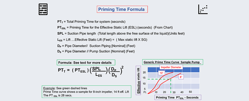
Next is the priming time for the effective static lift. This information will come from the pump manufacturer and is based on empirical test data for the pump. This information is based on a suction pipe diameter that is the same size as the nominal pump suction. Consequently, if the suction pipe is bigger than the pump suction, the prime-time calculation will be incorrect. Also, be sure to use the effective static lift (corrected for SG in lieu of the static lift). See chart on Image 1.
The vapor pressure of the liquid (a function of the liquid temperature) is not part of the formula but will be required for the NPSHa calculation. Assume worse case for computations, meaning the highest liquid temperature you will expect in the system.
If liquid temperatures will approach 140 F, that will be a red flag that you are coming close to the boundaries of physics and the pump limits. As grandma used to say, “a pump has to know its limitations.” For more details, see my October 2021 column on rethinking the NPSHa matrix: www.pumpsandsystems.com/rethinking-npsh-matrix?oly_enc_id=0806C1425778F5U
Example
An example pump system has been verified to have both sufficient NPSH and critical submergence margins. Using the formula with inset chart in Image 1, and some provided sample information, see if you can calculate the priming time for this test pump manufactured by the fictional Acme Canis Latrans Pump Company LLC based in northern Arizona.
GIVEN: a model “Geococcyx Californianus” self-primer pump lifting water at 68 F (SG=1.0) with an 8-inch impeller. The suction pipe is the same diameter as the pump suction inlet which is 3 inches (0.250 feet). The suction lift is 14 feet, and the total suction pipe length above the surface is 18 feet. Using the formula and the chart in figure one, the answer for total priming time will be 36 seconds.
NOTE: if we change the example to where the suction pipe is enlarged from 3 to 4 inches the total time changes from 36 seconds to 64 seconds.
Final Tips
Over the years, I have collected my own list of the most common reasons as to why self-primer pumps will not operate properly. An abridged and succinct list follows:
- First prime, the pump was not initially primed.
- Reprime, the pump requires reprime after transport, maintenance or evaporation.
- Lift is too high. Any lift over 25 feet should be scrutinized.
- Suction source too far from the pump.
- Leak in suction. The water does not leak out, the air leaks in.
- No air vent.
- High point in the suction line prior to the pump will create an air lock.
- Strainers will clog and/or add too
- much friction.
- Foot valve, covered in this column.
- Pipe size, covered in this column.
- Temperature of liquid exceeds 145 to 160 F. Liquid will flash.
- Submergence, if insufficient, will induce air entrainment.
- NPSH margin, if insufficient, causes cavitation.
- Freeze damage. There is water sitting in the priming chamber that expands when temperatures drop below freezing and will crack the casing.
- Reverse rotation, the pump will fail to operate properly.
- Flocculants or surfactants in liquid will create foaming in the priming chamber preventing the priming process.
- Excessive clearance from wear or improper setting.
