

Vertical turbine pumps (VTP) commonly have rotors with multiple mixed-flow impellers (sometimes 12 or more) that are supported by a vertical pump motor. Such designs offer a lift adjustment for raising or lowering the pump rotor to properly position the impellers within the bowl. Depending on the type of pump, this may be critical for maximizing pump efficiency and could have a significant impact on motor load (current) and reliability. Given the importance of VTP lift adjustments, it is necessary to recognize that procedures vary with the characteristics of the pump and motor.
Solid-Shaft vs. Hollow-Shaft Motors
Vertical pump motors can include a solid shaft or a hollow shaft. Solid-shaft designs provide a standard keyway that engages a solid coupling to drive the pump, plus an annular keyway that accepts a split ring key to support the pump rotor. Hollow-shaft motors drive and support the pump rotor from the top by means of a head shaft that passes through the hollow motor shaft and connects to the pump line shaft. In either case, there is an adjustment that lifts the pump rotor to ensure it is supported by the motor shaft.
Lift Adjustment Space
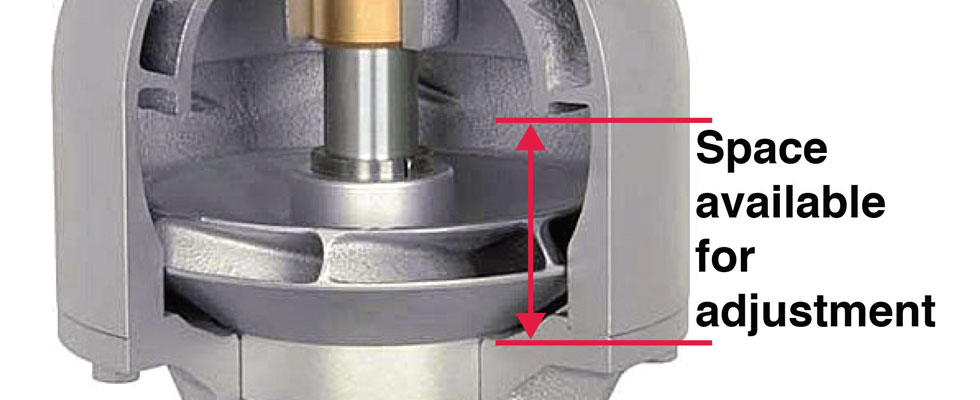
The space available for the lift adjustment is from where the impeller sits on the bottom of the bowl to where it would rub on the top of the bowl (Image 1). When assembling a VTP, it is important to locate each impeller on the pump shaft so that it rests on the bottom of the pump bowl when the pump is vertical or there will be less room for adjustment. The first step in setting the lift adjustment is to determine the available space. Measure the line shaft height with the VTP in the vertical position and the impellers resting on the bottom of the bowls. Then, lift the pump rotor until the impellers rub the top of the bowls and note the change in the line shaft height. The operating height must be between these two dimensions.
Closed or Open Impellers
The first concern in setting the lift is whether the impellers are closed style or open style.
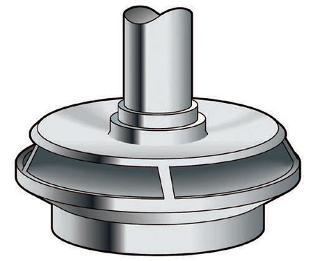 IMAGE 2: Closed impeller with suction eye wear ring
Closed impellers. These have a front shroud and may have a suction eye wear ring (Image 2). The lift adjustment for closed impellers with suction eye wear rings is less critical than for open impellers. Generally, it does not affect pump performance.
Open impellers. Open impellers include vanes exposed on the suction side (Image 3). The adjustment for these impellers significantly affects pump performance because the clearance between the open vanes and the bottom of the bowl affects the pump efficiency.
Note: Some VTPs have a single, axial-flow impeller with a bowl design that provides a large space above and below the impeller. The lift adjustment for these pumps is less critical than for open impellers and has no effect on pump performance.
Short-Set or Deep-Set VTPs
The next concern for the lift adjustment is whether the VTP is short-set or deep-set.
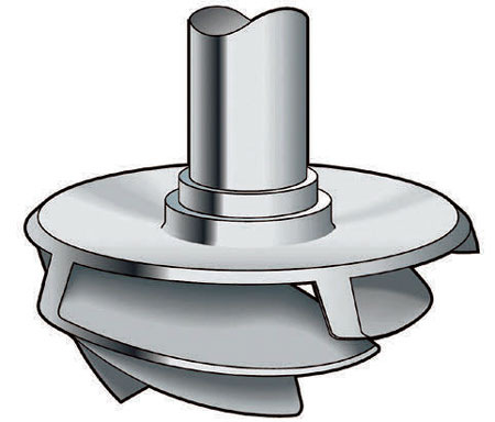 IMAGE 3: Open mixed flow impeller
Short-set VTPs. While there is no specific length designation, a short-set pump is one that can be handled (installed or removed) as a single piece.
Deep- or long-set VTPs. These pumps may extend hundreds of feet below grade and require assembly or disassembly at the jobsite. Usually, when the depth below grade exceeds 100 feet (30 meters), shaft elongation must be considered in setting the lift adjustment.
Calculating the amount of shaft elongation is not a trivial task since the downthrust on the impellers varies with the discharge head (or total dynamic head [TDH]). Fortunately, pump manufacturers calculate the shaft elongation when sizing the pump for the application.
Setting the Lift Adjustment
The primary objective in setting the lift adjustment is to place the impeller at a vertical position in the bowl where it will operate without rubbing on the bottom or top.
For closed impellers with suction eye wear rings, that is essentially the only concern. However, for open impellers or closed impellers without suction eye wear rings, the clearance between the bottom of the bowl and the impeller also impacts pump efficiency and motor load (current).
Increasing the clearance at the bottom of the impeller reduces the efficiency of the pump and decreases the motor load.
Although it is common practice to address motor overload conditions by increasing the lift adjustment, this does not work for closed impellers with suction eye wear rings.
The details of setting VTP lift adjustments depend on the characteristics of the pump and motor. For a short-set VTP with a closed impeller and a suction eye wear ring, it is relatively simple. Just position the impeller so it does not rub the top or bottom of the bowl. But the lift adjustment for an open impeller on a 250-foot (75-meter) deep pump will require the pump manufacturer’s shaft elongation calculations to avoid catastrophic failure.
And remember, trying to fix an overloaded pump motor by increasing the lift clearance results in an efficiency loss, thus increasing operating costs over the long haul. If in doubt about how to proceed, most manufacturers can provide step-by-step instructions for specific pumps.
