

When equipment is sent out for refurbishment, the expectation is that mechanical and hydraulic performance upon reinstallation will be better than what was experienced in the worn condition. This assumption holds true in most cases; however, unexpected behavior can occur after a pump is remanufactured and reinstalled. While it is easy to jump to
the conclusion these performance changes were caused by errors made during the repair or installation of the equipment, sometimes the problem is more complex and related to latent weaknesses in the design that had lain dormant until refurbishment.
No pump can be returned to the same condition as when it was first purchased. Although equipment can be returned to “like new” condition, there will always be slight changes in the stiffness and mass induced by the machining and welding processes performed when returning the equipment to optimal operating conditions. While under most circumstances these changes will not have any impact, in a design that is operating on a razor’s edge between acceptable performance and the excitation of a resonant condition, these changes can make a world of difference.
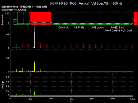
IMAGE 1: Vibration data collected by end user after commissioning (Images courtesy of Hydro, Inc.)
It is important to understand a newly refurbished, poorly performing pump may not actually indicate there was a problem with the repair. It is natural to assume the pump should be returned to the repair vendor as a warranty, but this could lead to taking the equipment out of service unnecessarily and not addressing the underlying problem. Taking the time to collect comprehensive field data and perform a robust causal analysis will provide significant long-term benefits by effectively diagnosing the problem and preventing its recurrence.
This scenario was experienced by a power utility in the southeastern United States when they ran into significant vibration increases after one of their boiler feed pumps was refurbished by a local repair shop. Concerned by the level of vibration, the utility reached out to an independent aftermarket service company they had worked with frequently and knew had extensive experience with this application. The aftermarket company had a division dedicated to performing field testing and troubleshooting, which could collect data on the problematic equipment and use advanced modeling tools to understand the nature of the vibration. The field testing and analysis revealed the pump had been operating with a small margin between a structural resonance and one of the pump forcing frequencies. Armed with this information, solutions were developed to increase this margin and return to stable operation.
Initial Testing & Installation Adjustments
The pump in question is a 10-stage axially split opposed impeller boiler feed pump. The first stage impeller has four vanes, and the series stage impellers have five vanes, resulting in two vane pass frequencies—4X rotations per minute (rpm) and 5X rpm. The vibration was measured at 1.0 inches per second (IPS) 0-Peak, with a dominant peak at the 4X frequency (1X vane pass frequency for the first stage impeller). The pump was installed on Unit 2 of the plant and operated as a 100% pump. The sister pump installed on Unit 1 did not exhibit the same high vibration.
Common root causes for high vibration at vane pass for this pump configuration include impact loading of the fluid exiting the impeller and striking the stationary volute cutwater, acoustic resonance in the crossover passage and excitation of a structural resonant frequency. Because the heightened vibration did not exist prior to refurbishment and reinstallation, the most likely cause was a structural resonance. Additionally, the 4X rpm frequency exhibited a body of energy at
the base of the peak and was highly directional, which are both characteristic of a resonant excitation.
The aftermarket service provider’s reliability division determined impact testing was the best first step in diagnosing and resolving the vibration issue. Impact testing, or an operational deflection shape (ODS), is typically performed on equipment while it is not running. A calibrated modal hammer is used to impact the structure, providing a quick pulse of broadly based energy. The calibrated modal hammer provides force in, while accelerometers read response out, allowing the field engineer to obtain a frequency response function (FRF). Through this process, the structural natural frequencies can be identified.
Prior to arrival on-site, they were informed all four feet of the boiler feed pump had been torqued to the full torque value during installation. No thermal expansion gib blocks were found on either the Unit 1 or Unit 2 boiler feed pumps. This goes against common practice, where the thrust-end feet are typically allowed to move axially, allowing for thermal expansion as the pump comes up to temperature. The decision was made to impact test the equipment both with the feet fully torqued and with the feet released. Releasing the thrust-end feet would decrease the stiffness of the installation and shift the natural frequencies. The intent of this plan was to determine how much of a softening effect releasing the feet would have on the installation, with the hope it would move operation out of the suspected natural frequency excitation range.
With all four pump feet torqued to the full value, the collected FRFs identified a structural resonance at the outboard bearing housing at 217 hertz (Hz), which has a -9.28% margin of separation from the first stage 4X vane pass frequency of 239 Hz. Best practices maintain a minimum +/-15% margin between forcing functions and natural frequencies to avoid excitation of a resonance. Testing with the thrust-end pump feet released revealed the identified resonant mode shifted to a slightly lower frequency of 207 Hz; this provided a -13.46% margin of separation, which was an improvement, but still not within the recommended +/-15% margin. Comparison impact testing was performed on the Unit 1 boiler feed pump. The correlating resonant mode on this pump was identified at 197 Hz. At a -17.64% margin of separation, this meets acceptable margin criteria and explains why the high vibration condition was not being experienced on the other unit.
The plant decided to install thermal expansion gib blocks and collect vibration data while the pump was running to see how the increase in margin from -9.28% to -13.46% affected pump vibration. This change would have the collateral benefit of ensuring the casing was able to expand as it came up to temperature, mitigating any risk of warping.
After the gib blocks were installed, vibration was recorded as the unit came online. The vibration at the outboard vertical location reduced significantly from approximately 1.0 IPS 0-Peak to approximately 0.35 IPS 0-Peak. While this was a substantial decrease in amplitude, the vibration still marginally exceeded the 0.3 IPS 0-Peak recommended alarm for this size pump.
Modal Analysis & Solution Development
After it was determined that releasing the thrust-end feet did not provide sufficient reduction in overall vibration, the site and aftermarket service company decided performing an offline modal analysis was the next necessary step. The purpose of this test is to identify the natural frequencies present below 800 Hz and their associated mode shapes, determine each mode’s proximity to excitation and understand the damping and amplification properties. The testing was performed by attaching a total of 18 tri-axial accelerometers to the pump casing and bearing housings and impacting the structure with a 3-pound (lb.) modal hammer equipped with a 5,000 pound of force (lbf.) force transducer. The captured FRFs were imported into MEScope Visual Modal software for curve fitting and animation.
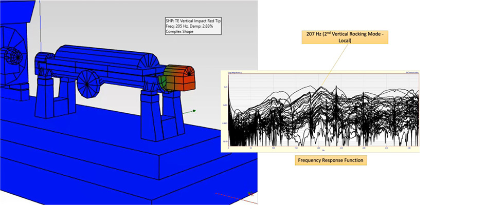
IMAGE 2: Second vertical rocking mode
Understanding the mode shape of the resonance supports creating the most effective design changes to resolve the problem. In this case, the mode at 207 Hz was an isolated rocking mode, which indicated changes needed to be made directly to the bearing housing, as the entire structure was not participating in the resonant excitation.
Armed with more information on the offending mode, four proposed courses of action were developed. Two of these four options would require removing the equipment from the field. The first of these was to complete a finite element analysis (FEA). Theoretic structural modifications would be applied to the FEA software model to determine what modifications would shift the frequencies out of excitation range without exciting a secondary resonance. Another option was to redesign the first stage impeller to have a different vane count, removing the 4X rpm forcing function. Neither of these options were pursued, as the site had a strong preference not to remove the equipment unless there were no other viable alternatives.
The options available that did not require removing the pump from the field were to modify the pump in the field by adding mass and designing a dynamic vibration absorber (DVA). It was determined the best course of action was to design and manufacture a DVA.
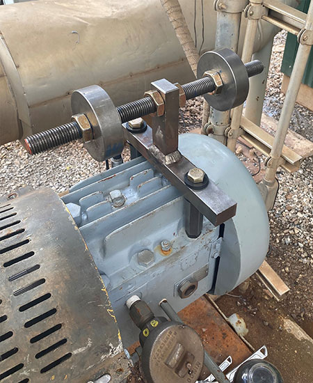
IMAGE 3: Dynamic vibration absorber with
two masses
A DVA works by having an identical natural frequency as the system to which it is mounted but vibrating in an opposing phase. The opposing motions cancel out the resonant amplification. DVAs do require periodic resetting, as the mass attached may move over time and change its natural frequency; however, the successful installation of a DVA would allow the pump to be placed back in service quickly and operate with reduced vibration while a more permanent solution is developed.
The DVA was initially designed and mounted with a single mass. This DVA was able to reduce vibration to 0.2 IPS 0-Peak from 0.35 IPS 0-Peak. A second mass was added to the DVA, which was successful in reducing the vibration down to 0.11 IPS 0-Peak. The DVA was designed to allow removal without having to readjust the mass, facilitating seal and bearing maintenance.
Resonance is a complex problem and can often be overlooked as the cause of vibration problems in cases where an otherwise unproblematic refurbishment or installation shifts equipment into an excitation range. Resolving resonance can be equally complex, as efforts to change the dynamics of an installation or change the forcing function through a new vane combination are expensive and would likely require the equipment to be out of service for a considerable amount of time.
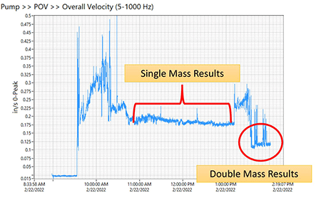
IMAGE 4: Vibration reduction with single mass and double mass DVA
By using a combination of field testing and analytical modeling, a clear picture of the nature of the vibration can be developed and any dormant risks identified. This allows a solution to be developed that is both effective and cost effective, minimizing the investment in time, labor and money to resolve the problem and ensuring the equipment is returned to a safe and reliable operating condition.
