

Shaft alignment is a critical step in the installation of rotating machinery, in a new installation or a repaired machine. Skipping or botching this step can decrease operating efficiency and shorten machine life. The procedure for aligning two rotating machines requires measuring their relative shaft positions and adjusting one or both machine cases, usually by shimming at the feet. Until recently, though, how closely the shafts need to be aligned was an open question. That changed with the publication of American National Standards Institute/Acoustical Society of America (ANSI/ASA) standard 2.75-17. Here is a summary of what it covers and how it will benefit users involved with shaft machinery alignment.
The Need for a Standard
Before going further, it is important to acknowledge that ANSI/ASA S2.75-17 represents a big step forward. Previously, there was no industry-wide standard for setting shaft alignment tolerances and best practices; so, the task fell to machinery manufacturers and organizations focused on industry-specific applications.
For example, American Petroleum Institute (API) 670 provided shaft alignment tolerances for certain hydrodynamic pumps used in the petrochemical industry. Guidance on shaft alignment tolerances and best practices was developed by various industry mechanical engineering experts and by vendors of shaft alignment instruments. Although the most ubiquitous use similar methodologies and curves to illustrate tighter tolerances for higher speed machines, they vary considerably in allowable residual misalignment.
Purpose & Scope
In December 2013, the Vibration Institute and the ASA initiated a joint effort to create a universal, industry-wide shaft alignment standard. That effort culminated in 2017 with the publication of “ANSI/ASA S2.75-2017: Shaft Alignment Methodology, Parts 1 and 2. Part 1: General Principles, Methods, Practices, and Tolerances.” This standard addresses shaft alignment of the most common machine configuration: A horizontal machine with a driver and driven component, each with two bearings (a four-bearing set) and a flexible coupling between the shafts. “Part 2: Vocabulary” defines the terms used in Part 1. Part 3, which is slated for publication in 2022, will address shaft alignment of vertical machines.
Besides guidance on shaft alignment tolerances, ANSI/ASA S2.75-2017 provides methodology for manual and laser measurements. It also establishes alignment quality grades, describes best practice for corrective moves and addresses basic mounting and base issues. Additionally, the document includes several informative annexes, including:
- alignment principles
- machine move calculation formulas
- identifying and correcting pipe strain
- off-line-to-running (OLTR) methods
- laser detector systems
- graphic alignment modeling
- repeatability
- alignment and machinery installation checklist
Tolerances
Among the fundamental concerns ANSI/ASA S2.75-2017 addresses are acceptable relative shaft position (shaft alignment) tolerances. It also prescribes tolerances for other critical factors such as base flatness and level, shaft runout, coupling runout, soft foot and OLTR machinery movement.
In addition, the standard specifies a tolerance for pipe and conduit strain, which “shall not be sufficient to cause changes in the shaft alignment of magnitude greater than 50 micrometers (2 mils; mil = 1/1000 of an inch) vertical or horizontal measured at the coupling.” The included Annex C provides a methodology for identifying and correcting this condition when aligning pump shafts.
Alignment Principles
Importantly, ANSI/ASA S2.75-2017 provides a comprehensive approach to the shaft alignment process, including a flow chart that shows key steps and decision points.
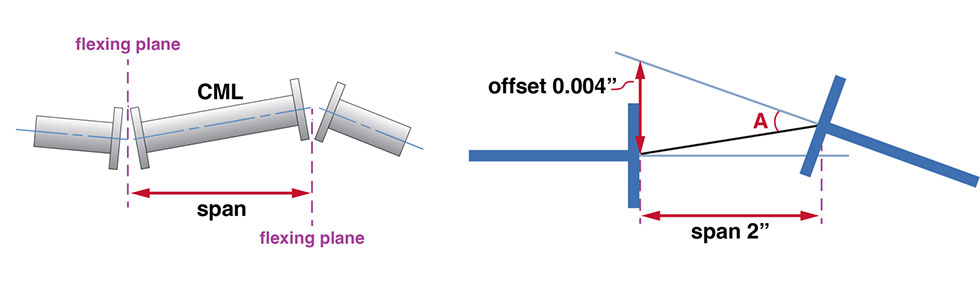
Of the two common methods for evaluating shaft-to-shaft alignment (see top rotator image), one uses the offset and angularity between shaft centerlines to indicate alignment. The other evaluates the offset at each of the two coupling faces relative to the distance between them, yielding a pair of angles described in mils of offset/inches of separation (mils/in or µm/mm).
ANSI/ASA S2.75-2017 refers to the flexible member between the coupling hubs as a coupling mechanical link (CML). The angularity between the CML and each hub that occurs at a point called the flex plane accommodates the shaft-to-shaft misalignment. Because these two flex plane angles represent the work done by flexible coupling more accurately than offset and angularity values, ANSI/ASA S2.75-2017 uses this method to establish alignment tolerances.
Another advantage of this method is that it reduces the tolerance required at both flex planes from two values (an offset and an angle) to a single angle, making it easier to achieve.
Alignment Quality Grades
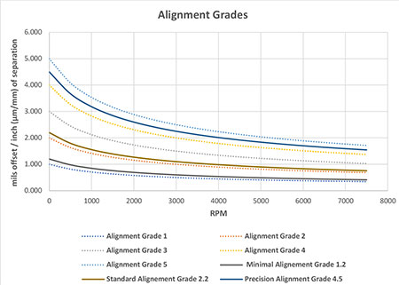
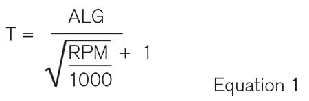
ANSI/ASA S2.75-2017 provides alignment quality grades in units of mils/in (µm/mm) based on machine operating speed and flex plane angles, directly related to the ratio of the offset at the flex plane to the flex plane separation. The tolerances are provided in tables and graphically on an alignment grades chart (Image 1). They also can be calculated by the formula in Equation 1.
The chart highlights three alignment grades: AL4.5 = minimal; AL2.2 = acceptable; and AL1.2 = excellent. A machine manufacturer, service provider or end user can choose any alignment grade based on machine construction and operating condition, independent of operating speed. So, a pump manufacturer that builds sturdy machines for rough service might specify AL2.0 for its machines, whereas a machine tool manufacturer desiring exceptionally smooth operation may specify AL1.0. A manufacturing plant could specify AL1.2 for newly installed machines but allow AL2.2 when boundary conditions (e.g., bolt bound or base bound) limit machine moves.
For example, a coupling alignment offset measurement (reverse dial indicator or laser system) of 0.004 inch at one flex plane and a flex plane separation of 2 inches would be a ratio of 4 mils/2 inches = 2 mils/inch (Image 4). The alignment grades chart (Image 3) shows that at 1,800 rotations per minute (rpm), a flex plane angle of 2 mils/in is above AL2.2 and below AL4.5. To improve this alignment to AL1.2, both flex plane angles must be less than 0.72 mils/in, with an actual measured offset of less than 1.44 mils at each flex plane. These values can be calculated from the formula mentioned earlier. Note: Both flex plane angles must be within tolerance so it is only necessary to evaluate the greater of the two.
Many alignment technicians are familiar with the tolerance tables various alignment tool vendors provide. Usually, these tables give shaft centerline offset and angularity values for common machine rpms when the coupling hub separation is less than 4 inches and offset values at the coupling hub when separation is greater than 4 inches. This method represents a compromise between concerns about the forces that misalignment imposes on couplings and the desire to have tolerances in the format that was popular when coupling alignment was done only with straight edges and feeler gauges.
For convenience, ANSI/ASA S2.75-2017 provides tables in the offset and angularity format with values that correspond to its AL4.5 minimal, AL2.2 acceptable and AL1.2 excellent tolerances. Meeting those values will ensure conformity with corresponding tolerances in the standard, but the geometric differences between tolerance formats may result in closer alignment than necessary. While that is not bad for the machine, it may take extra time and effort.
Making Machine Moves
ANSI/ASA S2.75-2017 is not a training manual, but it does provide information and guidelines for moving machine cases—a step in the alignment process that can be frustrated by such issues as soft foot and base-bound or bolt-bound conditions. For example, it mentions jacking screws and related techniques for adjusting machine position in a controlled manner and addresses the importance of positioning axial spacing (coupling gap). Though limited in scope, this information will be helpful to alignment technicians who encounter these issues.
The absence of a comprehensive shaft alignment standard has been a stumbling block to creating effective training and work procedures. ANSI/ASA S2.75-2017 marks a new day for end users, instrument vendors and consultants involved with machinery shaft alignment. With a comprehensive standard, produced with input from a broad array of machinery technical experts, work procedures and technical specifications can agree, and shaft alignment technicians will not have to rely on a patchwork of best practices and sometimes erroneous rules of thumb.
Part 1 of ANSI/ASA S2.75-2017 addresses alignment of common four-bearing sets with flexible couplings, and soon-to-be-published Part 3 will cover vertical machines that often have solid couplings or Cardan shaft drives. While additional parts may be forthcoming, together Parts 1 and 3 will encompass the major segment of common industrial machines.
