Proper calculations generate additional power.
NRG Energy, Inc.

Editor’s Note: This case study is provided by a pump advisor for Turbomachinery Lab at Texas A&M where students are exposed to hands-on experiences, providing them pump training in the field. In this article, students learn the importance of doing the math.

A call came from a regional engineering manager in a Connecticut-based facility two winters ago, inquiring about an operational issue with a No. 2 fuel oil pump feeding a power generation boiler. It would not pump like it should.

The problem had a sudden onset, which coincided with a dramatic flow rate drop, increased vibration, loud noises and overheated pump case. This was all amid a cold spell, when it was necessary to generate additional power.

After some discussion about the layout and the symptoms, the “why” became clear. The cold weather caused the viscosity of the fuel oil in the long, outdoor suction line to increase until the net positive suction head required (NPSHr) by the pump could no longer be met. It was an NPSH problem.

suction piping
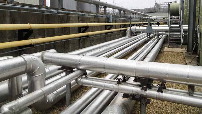
Image 1. Long suction piping from horizontal tank in background (Images courtesy of NRG Energy, Inc.)

A site visit was required to assess what to do about this NPSH inadequacy. The problem was evident. Whereas best practices guidelines would contain wording such as “keep the distance between the suction tank and pump as short as possible,” this layout was different. Compounding the problem, no source for heat tracing of the 260-foot suction line (electrical or steam) was readily available.

The only practical solution was to either replace the entire suction line with a larger diameter line or to install a second, parallel suction line to reduce the friction head loss. Both options would carry a price tag of more than $100,000. There was no easy solution. More research was needed.

To determine the appropriate diameters required for each option, the system was modeled using pump and pipe hydraulic modeling software. An unexpected problem arose—despite the increased viscosity and the long suction line, the impact on NPSH available (NPSHa) was still such that the margin (NPSH3) required by the pump could not be met.

Clearly, this was not correct. The team thought a computer error had to be responsible. The calculation was run by hand, and the software output result was confirmed. Then, in researching the behavior of No. 2 fuel oil further, the tendency of the fuel oil to wax, or gel, in extremely cold conditions was discovered.

double suction
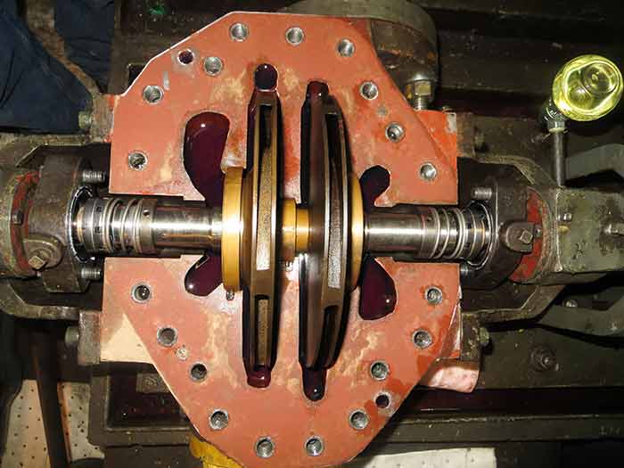
Image 2. Lower half of a double suction, two-stage pump

And that was the real problem. The viscosity did not only increase to the point that friction head losses became excessive, but the exposed pipe wall temperature had dropped low enough to allow the fuel oil to develop wax against the inner pipe wall and propagate radially inward. The slow-flowing liquid in the pipe had lost enough heat to reduce the active hydraulic diameter of the pipe further, to the extent that NPSH3 could no longer be met.

The plan was to increase the suction line capacity to reduce friction losses, which would slow the linear velocity in this line down even further. This would increase fluid residence time even more, and thereby further increase the tendency and opportunity to wax.

A double suction, two-stage pump was used to provide No. 2 fuel oil to the boiler (see Image 2 and 3). Since the flow rate required by the boiler was low, yet the pump dynamic head required high, the boiler flow rate constitutes an uncomfortable duty for a centrifugal pump—even for pumps with low specific speeds. It was found that the boiler flow rate was the only flow through the pump, at 25 percent best efficiency point (BEP). The minimum flow recirculation (routed back to the fuel oil tank) was essentially inoperative, because a pressure relief valve was ineffective in a flat part of the curve and the activation pressure had been set too high. The preferred option (an in-line flow meter) was not available.

With the pump operating at only 25 percent BEP and the minimum flow recirculation line inactive, the optimal solution also became apparent.

pump design
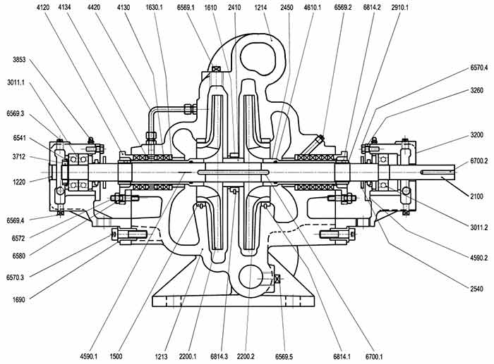
Image 3. Pump design; two stages

Contrary to first instinct, the solution here was not to increase the suction line diameter and capacity to decrease friction head losses, but the exact opposite: increase the flow rate and linear velocity.

A small modification would be required to activate the minimum flow recirculation by opening a bypass valve to an appropriate setting on a permanent basis to act as a minimum flow orifice. The residence time would be reduced and heat loss to the environment reduced, such that waxing would be delayed.

System modifications in this scenario are not too difficult to implement. The solution would have two-fold benefits: NPSHa will be improved and the operating point on the pump performance curve will improve, and reliability of the centrifugal pump improved as a direct consequence.

Once the math was calculated and the optimal solution determined, a win-win solution was determined:

  • Residence time in the suction pipe exposed to the cold was reduced, thereby reducing the risk of waxing.
  • The pump minimum flow recirculation was now activated and functional, such that the pump would run closer to 65 percent BEP. This was a significant improvement over the former 25 percent.
  • Major reliability improvements were made possible for minimal investment.

It is important to note not only the technical details of this problem and its solution, but also to realize how easy it is to make inaccurate assumptions and to draw incorrect conclusions. Use facts to draw conclusions. In this case, initial assumptions would have caused the implementation of a modification that would have guaranteed failure.

The major lesson learned here is to do the math. It is less expensive than the results of a mistake, and easier on future career aspirations.