The wastewater industry has always demanded reliable solutions for handling solids-laden fluids. In the mid-1900s, one such innovation emerged out of necessity: the chopper pump. Designed to address persistent plugging problems in dairy wastewater systems, chopper pumps quickly gained traction for their ability to process solids that traditional pumps could not handle. Over the decades, the combination of mechanical innovation and digital tools like computational fluid dynamics (CFD) has transformed how chopper pumps are designed, tested and implemented across wastewater treatment applications.
The Role & Evolution of Chopper Pumps
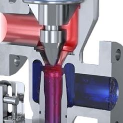
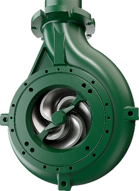
Chopper pumps are centrifugal pumps equipped with chopping features that reduce the size of solids in various waste streams—including municipal sewage, food waste, industrial waste and agricultural waste. These pumps employ sharp impeller vanes that rotate past stationary cutter bars at the suction inlet, effectively chopping solids before they are pumped out.
In hydraulic mixing systems, chopper pumps serve dual roles: reducing solids and maintaining homogeneity in municipal digesters and numerous other sludge and slurry tanks. Maintaining a homogenous mixture is essential for optimizing biological treatment processes like anaerobic digestion. The microorganisms turn organic waste into biogas and safe, nutrient-rich digestate. These microorganisms perform at their best when there is a steady supply of organic waste moving past them. CFD allows users to determine optimum nozzle placement and optimum mixing flow for peak digester performance.
The increasing prevalence of flushable wipes and low flow toilets over the past two decades has intensified clogging issues in traditional sewage systems. As a result, chopper pumps have become critical components in modern wastewater management, helping mitigate operational disruptions and improve equipment longevity.
The Introduction of CFD
In the 1990s and 2000s, the wastewater industry began harnessing the power of CFD—software that simulates fluid flow in engineered systems. For pump and equipment manufacturers, CFD opened new avenues to optimize component design, mixing patterns and tank geometries without the high cost and time associated with physical prototyping.
Prior to CFD, pump design was often based on theoretical calculations and limited by manual prototype testing. Design iterations were minimal due to the expense of casting and machining unique parts. Rapid prototyping via 3D printing, which became more accessible around 2010, has helped—but even today, large-format prints or casting patterns remain costly.
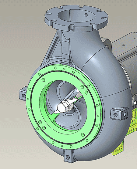
Because of CFD, engineers can now simulate dozens of impeller geometries, volute shapes and suction configurations virtually, before investing in a single physical part. However, CFD is only as good as its real-world validation. Over time, manufacturers developed precise modeling techniques and mesh strategies to ensure simulation results accurately predicted physical pump performance.
CFD in Pump Design: A Case Study
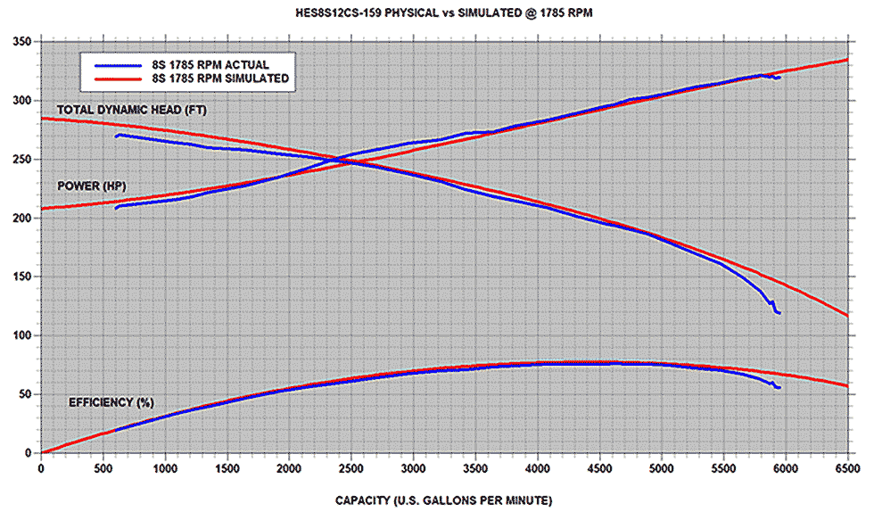
One pump manufacturer that has been using CFD modeling combined with rigorous testing and validation work for over 22 years has found it allows them to design new pump models with CFD simulations matching real laboratory results to within a few percentage points. This level of accuracy—achieved through repeated refinement and empirical correlation—has allowed new pump designs to move confidently from simulation to production.
Since standard pump performance testing uses clear water, CFD simulations do the same. While this may seem limiting, decades of experience with chopper pump applications allow engineers to design blades that balance cutting efficiency and hydraulic performance based on CFD data and field knowledge.
While a fully clogged pump is clearly inefficient, a partially clogged pump—often harder to detect—can be even more detrimental to performance. Maintaining high hydraulic efficiency without compromising chopping capability is critical. CFD enables engineers to optimize both.
CFD & Hydraulic Mixing System Design
CFD is indispensable in designing effective hydraulic mixing systems. Early simulations revealed how nozzle placement, angle and velocity affect flow patterns and fluid velocity distribution within tanks. This understanding helped engineers develop tailored mixing strategies for cylindrical, rectangular and irregularly shaped tanks.
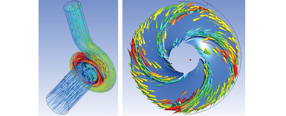
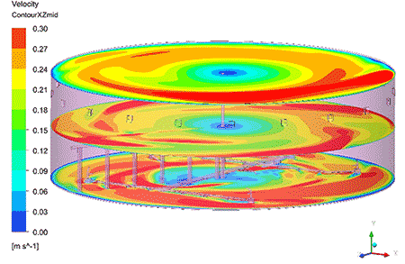
One of the most powerful benefits of CFD is its ability to “look inside the tank.” Traditional field testing relies on limited sampling at discrete points, which may not reveal complete flow patterns. CFD simulations offer comprehensive visualizations such as:
- Velocity contour maps
- Streamline paths
- Tracer concentration over time
These tools help engineers understand how a fluid (or added tracer) moves through a tank, how it reaches the suction inlet and how quickly it recirculates through the system.
For example, simulating a tracer burst in a digester tank allows engineers to visualize mixing patterns, identify dead zones and detect short-circuiting between inlets and outlets. These insights guide nozzle placement, feed and withdrawal locations, pump sizing and control strategies, leading to more effective and energy-efficient systems.
Real-World Insights From Simulation
Simulations have shown that reaching steady-state conditions in large tanks, such as anaerobic digesters, can take up to an hour or more. Understanding this time-dependent behavior helps set realistic expectations for system performance and commissioning.
Accurate simulations require detailed modeling of internal tank geometry, including columns, corbels, existing piping and obstructions. These features can significantly influence mixing energy distribution and localized flow conditions.
Importantly, wastewater fluids are typically non-Newtonian, meaning their viscosity changes with respect to the fluid velocity. Different sludges, for example, can have widely different rheological properties. When unique viscosity characteristics are combined with the specific geometry of each tank, CFD becomes indispensable in determining the most efficient mixing system.
CFD allows engineers to input custom fluid models for each application, leading to better predictions of required pump power, mixing intensity and nozzle distribution.
In practice, higher-viscosity fluids demand higher-velocity mixing or more energy input from multiple points to prevent settling or scum formation. While a system may mix water effectively, the same setup may underperform with thick sludge. CFD helps quantify and correct for these differences.
Tracer Washout & System Validation
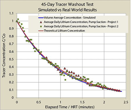
Tracer washout simulations have been invaluable for validating real-world mixing. By simulating a tracer’s movement through a tank—from injection at the pump suction and mixing nozzles, or from another feed location—engineers can compare simulated washout patterns with actual operational data, such as digester feed and bleed cycles.
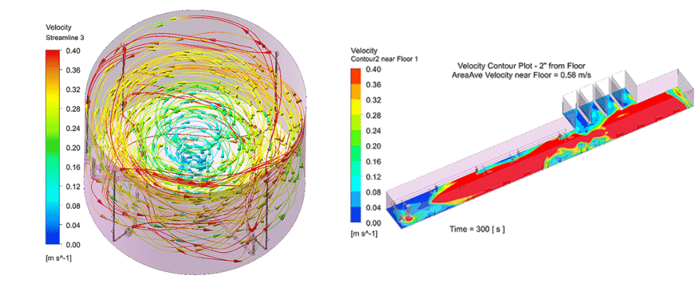
The strong correlation between simulated and observed tracer behavior reinforces CFD’s role as a predictive tool. Video footage and visual observations over the years have consistently mirrored the simulated velocity vectors and surface flow paths, lending confidence to design decisions based on CFD outputs.
Piping Systems & Suction Optimization
CFD is not limited to tanks. It also plays a vital role in analyzing fluid flow through piping systems. By modeling pipe networks, engineers can identify pressure drops, turbulence or uneven flow that could lead to cavitation or suction issues at the pump inlet. For example, CFD streamlines and pressure distribution plots can highlight areas where fittings cause energy loss or flow distortion. This allows for proactive redesign—such as smoothing transitions or resizing piping—to improve performance and efficiency.
The Future of CFD in Wastewater
Today, CFD is a cornerstone of engineering design in the wastewater sector. It allows manufacturers to:
- Optimize pump impeller/casing designs
- Analyze and refine tank mixing strategies
- Model non-Newtonian flow behaviors
- Design more efficient and cost-effective systems
- Correlate predicted performance with real-world testing
The synergy between chopper pump technology and CFD simulation has transformed how wastewater systems are designed and operated. By reducing solids, preventing clogging and ensuring homogenous fluid conditions, chopper pumps—backed by advanced simulation—have become critical tools in modern wastewater treatment.
From their roots as a solution to persistent pump clogging, chopper pumps have evolved into high-performance components thanks to decades of innovation and digital engineering. CFD has enabled engineers to understand complex flow behavior, improve design efficiency and develop robust systems that meet the increasing wastewater industry demands.
As treatment standards grow stricter and waste streams become more complex, the ability to simulate and optimize system behavior in a virtual environment will remain indispensable. By integrating mechanical expertise with digital tools like CFD, wastewater engineers can continue to innovate and adapt—ensuring cleaner, more efficient treatment solutions for the future.