
Q. What are the advantages of single, outside-mounted seals versus that of single, inside-mounted seals?
A. Single seals have one set of sealing surfaces. The lubricant for the seal faces is usually the pumped medium, and therefore, normal seal leakage will escape into the atmosphere surrounding the seal unless some type of containment is provided. Single seals can be mounted inside or outside the seal chamber and can have rotating or stationary springs.
The single, inside-mounted seal is the most common in the industry and the most energy-efficient when compared with other sealing methods, such as packing and sealless equipment. They are used in all industries with respect to fluid types and the seals’ property ranges, pressure speed, diameter and temperature.
Single, inside seals are mounted within the equipment seal chamber (see Figure 5.2). The advantages of this design include:
- The seal can be cooled by the pumped fluid in an enlarged dead-ended chamber, by a product bypass flush or by a clean external flush.
- Depending on the seal chamber design, the rotary action of the seal assembly may help keep debris away from the seal faces.
- With proper hydraulic balancing, the product pressure helps keep the seal faces closed.
- Catastrophic leakage is usually avoided during seal failure. Leakage can be restricted by the stationary elements in the gland.
- Inside seals are available in many materials and designs.
- Environmental controls are easily included in the design.
- Centrifugal forces tend to reduce leakage.
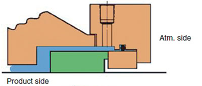 Figure 5.2. Inside-mounted, single seal
Single, outside seals are mounted external of the equipment housing (see Figure 5.3). The advantages of this design include:
- Outside-mounted seals can be used when the radial or axial space in the chamber is not adequate or access is not available for an inside seal installation.
- Installation may be easier than with an inside seal. However, most equipment designs still require some disassembly.
- Less expensive materials may be used since many components may not be exposed to the pumped product.
- The seal can be observed and monitored for seal face wear.
- Adjustments can be made without equipment disassembly.
- The seal can often be backed-off for cleaning.
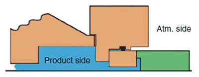 Figure 5.3. Outside-mounted, single seal
For more information about mechanical seals, see HI’s guidebook Mechanical Seals for Pumps: Application Guidelines.
Q. How can I determine the pump input power for a reciprocating pump?
A. Pump input power may be determined using transmission dynamometers, torsion dynamometers, strain gauge type torque-measuring devices, calibrated motors or other sufficiently accurate measuring devices.
When applicable, readings of power shall be taken at the same time that the flow rate is measured. Power input measurement methods fall into two general categories:
- Those that determine the actual power or torque delivered to the pump and are made during the test using some form of dynamometer or torque meter
- Those that determine the power input to the driving element, taking into account the driver efficiency when operating under specific conditions
When pump input power is determined by transmission dynamometers, the unloaded dynamometer shall be statically checked prior to the test by measuring the load reading deflection for a given torque and by taking the tare reading on the dynamometer scale at rated speed with the pump disconnected. After the test, the dynamometer should be rechecked to assure that no change has taken place. In the event of a change of ± 0.5 percent of the power at the best efficiency point (BEP), the test should be rerun. An accurate measurement of speed within ± 0.3 percent is essential.
The use of calibrated dynamometers or motors is an acceptable method for the measurement of input power to the pump. Calibration of the torsion dynamometer should be conducted with the torsion-indicating means in place. The indicator should be observed with a series of increasing loadings and then with a series of decreasing loadings. When taking readings with increasing loadings, the loading is at no time to be decreased. Similarly, during the decreasing of loadings, the loading should be based on the average of the increasing and decreasing loadings as determined by the calibration. If the difference in readings between increasing and decreasing loadings exceeds 1 percent, the torsion dynamometer shall be deemed unsatisfactory. Dynamometers shall not be employed for testing pumps with a maximum torque below one-quarter of the rated dynamometer torque.
When strain gauge torque measuring devices are used to determine the pump input horsepower, they shall be calibrated, with their accompanying instrumentation, at regular intervals (see Figure 6.72). After the test, the readout instrumentation balance shall be rechecked to ensure that no appreciable change has taken place. In the event of a change of ± 0.5 percent of the power at BEP, the test shall be rerun.
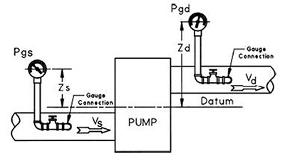 Figure 6.72. Gauge connections
Calibrated electric motors are satisfactory for determining the power input to the pump shaft. The electrical input to the motor is observed, and the observations are multiplied by the motor efficiency to determine the power input to the pump shaft. Calibrated laboratory type electric meters and transformers shall be used to measure power input to all motors.
For more information about this topic, see ANSI/HI 6.6 Reciprocating Pump Tests.
Q. What methods are used to cool a motor that drives a rotodynamic pump?
A. Many cooling methods can be used in motor design. When the cooling air is drawn from the surrounding environment, circulated around the internal components and expelled back into the surroundings, the cooling method is an open circuit. This type of cooling is only possible in open-enclosure motors.
Closed-circuit cooling involves an internal coolant in a closed loop that passes heat to another coolant either through the surface of the machine or with a heat exchanger. This type of cooling is by definition associated with totally enclosed machines because the primary coolant remains contained within the motor.
Most motors use shaft-mounted fans to circulate air as the primary coolant. One drawback of this approach is that the velocity at which the cooling air is circulated decreases if the speed of the motor decreases. In some applications, a constant velocity of air is necessary. In these cases, separately powered fans are often employed to deliver a regular velocity of air regardless of the motor’s rotational speed. While air is the most common fluid used as primary and/or secondary coolant in electric motor design, units can be built using others—such as refrigerant, hydrogen, nitrogen, carbon dioxide, water and oil.
VS0-style pumps, with the motor submerged, must have a minimum flow of cooling liquid past the motor during operation to properly dissipate heat. In applications such as open channels with a relatively low velocity of flow around the motor or installations in which the flow will not naturally flow past the motor, a flow sleeve needs to be installed to draw flow around the motor casing and protect the motor internals from overheating. For hot pumped liquid applications, consult the pump manufacturer.
For more information about motor cooling methods, see ANSI/HI 2.3 Rotodynamic Vertical Pumps of Radial, Mixed, and Axial Flow Types for Design and Application.
