

The purpose of testing is to verify the design of the product and ensure mechanical integrity. The test is completed to prove compliance with industry and client standards and to produce a final record of the pump’s performance under controlled conditions. In addition to the user’s specifications, certain industry standards are to be followed during the test. These standards are listed below.
- American Petroleum Institute (API) Standard 610, 12th edition
- Hydraulic Institute (HI) “Centrifugal Pump Tests,” American National Standards Institute (ANSI)/HI 1.6-2000
- HI “Vertical Pump Tests,” ANSI/HI 2.6-1994
- American Society of Mechanical Engineers (ASME) Power Test Codes (PTC), ASME PTC 8.2-1990
API 610 says that all API pumps sold to the standard will be performance tested. There are several classes for testing API pumps. Some tests listed are outside of the API standard but are occasionally required by the buyer. These classes are outlined as follows.
Mechanical run: A test to ensure the mechanical integrity of the pump. This means the pump will operate with no mechanical problems, which include maintaining acceptable bearing temperature, vibration levels and no leakage from the seals or gaskets. The duration of the test is only long enough to verify that the pump will operate satisfactorily in the field and the bearing temperature will stabilize.
A data point should be taken at the design condition to verify that the impeller trim is correct.
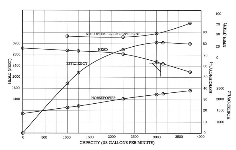
Performance test: A performance test is a complete test in compliance with API 610 specifications. Measurements are taken in compliance with the ASME PTC and the HI test standards. During the performance test, enough data is taken to fully define the curve, which is usually six or more points. Vibration is taken at each point as well as a running log of bearing temperature.
The pump must operate satisfactorily within the specified limits. The duration of the test should be long enough to stabilize the bearing temperature. The pump should be operated at field speed as shown on the data sheet unless agreed otherwise.
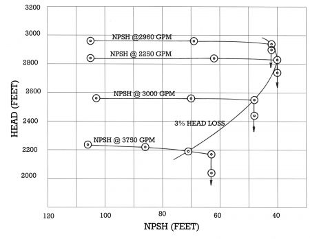
NPSH test: Net positive suction head (NPSH) testing is a test for determining the suction performance of a pump. To perform an NPSH test, pressure is gradually reduced in the suction line until the pump enters the onset of cavitation. This is usually defined by a 3% drop in head or, in the case of a multistage pump, a 3% drop in the first stage head.
Data points, which include the NPSH and pump total head, are taken until the total head begins to drop off. The capacity is maintained at a constant predetermined flow rate. For development tests, enough data should be collected to fully define the point where the pump ceases to operate. Image 2 shows a typical curve for a full NPSH test.
String test: A string test is a special test, usually requested by the client, where the pump and driver and possibly other drive train components, such as a gearbox, are set up, usually on the job base, and run as an assembly for a specified length of time.
The train is run at field speed unless otherwise specified, in which case a variable frequency drive (VFD) would be required. During the test, readings are taken as specified by the user and usually include: capacity, head, driver horsepower (hp) and vibration on all train components, the temperature of the component bearings and water temperature. This is a highly specialized test.
Witness test: Any of the above tests can be witnessed by the client. This is usually an extra-cost test. Typically, a standard test is run prior to the client witnessing the test to ensure that the pump is performing to expectations. Any problems found during the pretest can be corrected prior to the arrival of the client.
Instrumentation: All instrumentation used during testing must be of the highest accuracy and dependability, calibrated to national standards and traceable to the National Institute of Standards and Technology (NIST). Typical minimum accuracy for pressure and capacity instrumentation is +/- 0.1%. Horsepower readings will be at least +/- 0.5%.
During a test, a measurement will be made for capacity, suction head, discharge head, hp, speed, vibration and temperature (test water and bearings). Bearing temperature will include oil sump temperature and bearing temperature (sleeve bearings only). It simplifies testing if the pressure transducers (gauges) are calibrated in absolute pressure. Calibrating to absolute pressure simplifies head and NPSH calculations and removes the variations in atmospheric pressure, negating the need to take barometric pressure during the test.
At each capacity point, data is taken for suction and discharge head, hp and speed. The mechanical efficiency of the pump is calculated from these parameters. When required, an NPSH test is performed and the calculations are made to determine the NPSH. The formula used for these calculations is shown in Equation 1.
Head is calculated by the formula in Equation 1
H = Hdisch – Hsuction +
( V2disch/ 2g -V2suction/2g) +/- h
Where
H = total head of the pump in feet
Hdisch = the pressure head in feet (meters) absolute at the discharge pipe tap (pounds per square inch absolute [psia] at discharge pressure tap) /2.31 for water with a specific gravity of 1
Hsuction = The pressure head in feet (meters) absolute at the suction tap (psia at suction pressure tap) /2.31 for water with a specific gravity of 1
V2disch/2g = velocity head of the fluid in the discharge pipe (V = 0.00259 * gallons per minute [gpm]2/(ID)4) where the ID is in inches
V2suction/2g = velocity head of the fluid in the suction pipe (V = 0.00259 * gpm2/(ID)4) where the ID is in inches
g = gravitation constant of the earth (32.174 feet/sec2)
h = difference in the elevation of the suction and discharge pressure gauges, if any, in feet (meters)
Efficiency is calculated from the formula in Equation 2
Efficiency = Q * H/(hp* 3960)
Where
Q = capacity in U.S. gpm
H = head in feet of liquid (water)
hp = horsepower
3960 is the conversion factor for English units
For NPSH testing the formula for NPSH is in Equation 3
NPSH = ha + V2suction/ / 2g–hvp– hst
Where
ha = absolute pressure (in feet of liquid) measured at the pressure tap on the suction pipe.
V2Suction/2g = velocity head of the fluid in the suction pipe (V = 0.00259 * gpm2/(ID)4) where the ID is in inches.
hvp = the head in feet corresponding to the vapor pressure of the liquid at the temperature of the fluid being pumped
hst = the static head in feet that the suction pressure tap is above or below the centerline of the impeller or impeller eye
When testing with an induction motor, the motor speed decreases as the load increases. This is called slip as the speed slows down (slips from synchronous speed) as the hp increases. It is desirable to present the pump curves at a constant speed so the data (capacity, head and hp) need to be normalized to a constant speed.
This correction for speed is calculated using a relationship called the affinity laws. The laws state that capacity varies in proportion of the speed, head by the square of the speed and hp by the cube of the speed. This principle is used to correct all points taken during a test to a constant speed or to correct the data for pumps tested at a different speed than the speed listed on the data sheet.
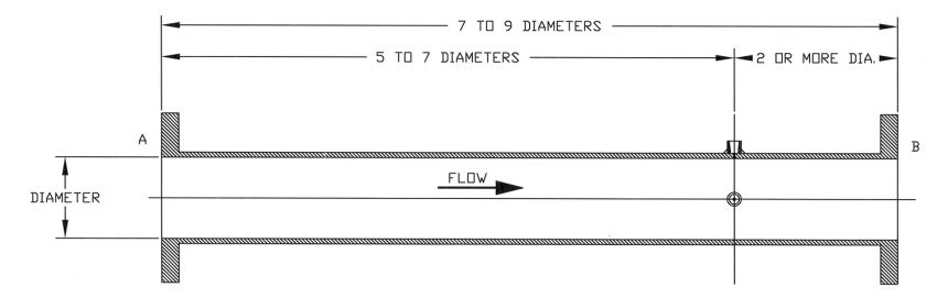
Suction and discharge piping must be designed according to the ASME PTC. Discharge pressure taps are located five to seven diameters from the flange (seven diameters preferred) and at least two diameters after the pressure tap. The purpose of this location is to allow the flow profile to equalize prior to taking the measurement. This means the connecting test pipes should be at least seven diameters long (nine diameters is preferred). The pressure tap is located two diameters before the suction flange and five to seven diameters after the discharge flange. The suction and discharge pipes must have a smooth inside diameter to prevent turbulence.
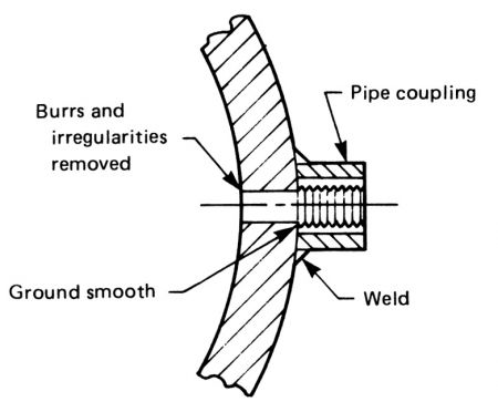
The pressure taps are located 90 degrees apart on the centerline. One tap will be used as a vent (set up on top centerline for non-self-venting pipes) and the other for pressure measurement located at the horizontal centerline. The pressure taps should be made in accordance with Image 1. The drill-through hole is an 1/8 inch and the connection is typically a 1/4-inch national pipe thread (NPT) half coupling.
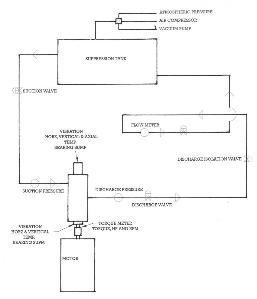
A typical test facility includes a closed-loop system where water is pumped from a suppression tank through a loop. Preferably, the tank is located below grade so NPSH testing can be performed with minimal throttling of the suction. During a test, water is drawn from the tank into the pump, then out the discharge of the pump where it flows through a control valve and flow meter before returning to the tank. See Image 4 for a schematic of test piping and instrumentation.
The suppression tank should be rated for at least 50 psi (150 psi preferred) and for absolute zero pressure vacuum. The tank pressure should be capable of being controlled from near absolute zero to 100 pounds per square inch absolute (psia) or more. Pressure is controlled using a vacuum pump and air compressor to produce the desired suction pressure. Horsepower is measured using either calibrated motors and watt meters or a torque meter.
Accurate speed readings are taken at each data point. This can be as simple as a strobe light and stopwatch where the strobe is set at the motor synchronous speed and the slips of the motor are counted and deducted from the synchronous speed. The most common option is a tachometer attached to the motor or included in the torque meter. Accuracy should be plus or minus 1 rotation per minute (rpm).
When observing a test, it is important that the witness fully understands what is happening. Although a performance test is highly specialized, it is not overly complicated. All major manufacturers and several independent repair shops have one or more test facilities.
References
American Petroleum Institute Standard 610, 12th edition
Hydraulic Institute “Centrifugal Pump Tests,” ANSI/HI 1.6-2000
Hydraulic Institute “Vertical Pump Tests,” ANSI/HI 2.6-1994
ASME Power Test Codes, ASME PTC 8.2-1990
