

Parallel pumping has emerged as one method of improving efficiency in pumping systems with higher control heads. With the advent of sensorless pump control technology, hydronic systems can be optimized for maximum system efficiency.
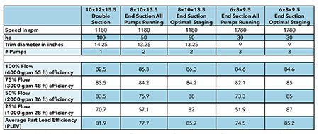 IMAGE 1: Table of part loads considering 100 percent flow at 1 percent; 75 percent flow at 42 percent; 50 percent flow at 45 percent; and 25 percent flow at 12 percent, considering no staging and optimal staging (Images courtesy of Bell & Gossett)
In a parallel pumping system, the controller makes decisions dynamically based on what the current flow and head requirements show.
While variable speed control in a parallel pumping system can increase efficiency and reduce costs, adding sensorless control technology to the pump staging process creates a solution that combines high efficiency, backup capacity and potential savings on space and initial investment.
In an environment where partial loading is the norm, optimizing system performance is not as simple as optimizing pump performance at a single duty point. The entire profile of the pump’s efficiency at varying flows and speeds must be considered. In a parallel pumping environment, this makes selection and staging strategies even more complex. Technology helps reach these solutions more easily, and parallel pump controllers with the best efficiency staging capability pay dividends.
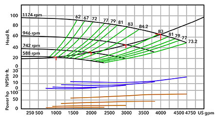 IMAGE 2: 10 x12 x15.5 double suction pump with 100-hp 6-pole motor
Selecting a pump for parallel operation using the same methods as choosing a single pump involves cutting the flow in half or a third and picking the most efficient option. When flow gets past 120 percent of best efficiency point (BEP), it is time to stage the next pump. However, that process does not leverage technology, and while the system will provide required head and flow, it likely will not be at optimal efficiency.
How can pump staging be truly optimized for efficiency? When examining different staging scenarios and comparing and contrasting the weighted part load efficiency values (PLEV), the challenges and solutions of designing parallel pumping systems become clear.
In the first scenario, the full load requirement is 4,000 gallons per minute (gpm) at 65 feet of head with a control head requirement of 19.5 feet. These design parameters should be carefully considered, as they dictate the system curve driving the selection decisions.
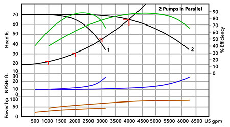 IMAGE 3: Two parallel 8 x10 x13.5 end suction pumps with 50-hp 6-pole motor
With such a large pump, the selection would likely be a double suction pump. In Image 2, the curve depicts an efficient solution, especially at full load. There is some tapering at 50 percent and 25 percent of load, yielding a weighted PLEV of 81.6 percent. This is a 10 x 12 x 15.5 pump with a 100-horsepower (hp), 6-pole motor—a large investment and footprint, but one that provides zero backup capacity.
The next option provides backup capacity and even greater PLEV. Image 3 shows two end suction pumps in parallel—8 x 10 x 13.5-inch pumps with 50-hp motors. This constant speed graph demonstrates efficiencies over 86 percent for portions of this curve, meaning there will only be improvements over the curves when variable speed is introduced into the equation. In general, the system curve crosses all of the test speed curves and demonstrates acceptable efficiencies.
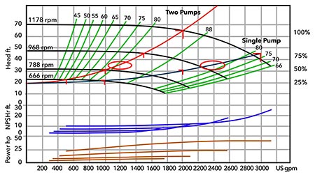 IMAGE 4: Single 8 x10 x13.5 end suction pump variable speed curve running as one of two pumps and solo at 100 percent, 75 percent, 50 percent and 25 percent of load
Image 4 reflects individual pump efficiency improvements created by variable speed. Dividing the flow between both pumps at full load, efficiency is 86.3 percent—even higher than the double suction pump in Image 2. If both pumps continue to run at partial loads, the weighted efficiency is 77 percent, below the double suction performance.
As demand decreases, the second pump must be destaged. As system requirements drop below 2,400 gpm, the two-pump efficiency is dropping below 80 percent, while the single-pump efficiency climbs to 88 percent as demand drops to 1,400 gpm.
Based on the system curve for this pump, it appears the best staging/destaging occurs around 10 percent past BEP. With two parallel pumps, one pump can drop off and the system will still operate at 75 percent capacity.
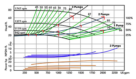 IMAGE 5: 6 x 8 x 9.5 end suction pump variable speed curve running in parallel as one of three pumps, one of two pumps, and solo at 100 percent, 75 percent, 50 percent and 25 percent of load
Image 5 demonstrates coverage up to 50 percent of load with one pump—if system losses have not been underestimated. With two pumps, nearly 90 percent of load is covered. In fact, if the requirement was to meet full duty with two pumps, motors and drives could be upsized to 40 hp and the pumps oversped to almost the same efficiency as the pumps in Image 5, just short of 60 feet at 2,000 gpm per pump.
Based on this pump’s efficiency profile, optimal system efficiency will be achieved by running two pumps from 3,600 gpm all the way down to just over 100 gpm or the 25 percent partial load point.
The initial investment savings on three 30-hp, 4-pole motors versus a 100-hp, 6-pole motor is 40 percent. The initial investment savings on three 6-inch pumps versus the single 10-inch pump is roughly 25 percent.
Image 1 (page 25) shows efficiency benefits that can be achieved by determining the optimal staging point for each parallel pumping solution. It is important to evaluate the system curve and pump efficiency curves to optimize staging.
In these scenarios, optimal staging in a parallel pumping solution can save 3 percent on energy costs versus the double suction solution while increasing backup capacity and potentially eliminating system downtime required for maintenance. But if pumps are not staged properly, the
system could operate 3 percent less efficiently than the single-pump solution, resulting in more than $1,000 in increased energy costs per year, depending on operating conditions and utility rates.
The staging points are based on system design and anticipated system losses. In these examples, the system is modeled using a system curve.
In actual application, this will need to be reviewed following commission. It should also be understood that in a diverse system, there is a control area rather than a simple control curve. The more diversity in the system, the larger this area and the greater the benefit from dynamic, real-time staging performed by a capable pump controller versus a fixed-staging strategy based on predetermined staging points.
Staging solutions for best efficiency can be complex, but with the aid of a parallel pump controller equipped with built-in best efficiency staging, calculations happen dynamically, ensuring the system can actually deliver these theoretical efficiencies.
Science Museum of Minnesota Achieves Unparalleled Energy Efficiency
Sustainability is a challenging pursuit for museums, which possess distinct building characteristics and other unique challenges like climate-controlled storage and gallery space to preserve irreplaceable exhibits. With the help of a parallel pump system, the Science Museum of Minnesota—a major destination for 700,000 visitors per year—is lowering energy costs and reducing its carbon footprint. Located in downtown St. Paul, the Science Museum of Minnesota has 370,000 square feet of space, including a 10,000-square-foot temporary exhibit gallery, five permanent galleries and an IMAX Convertible Dome Omnitheater. Following an energy analysis in 2018, the museum undertook several building upgrades to reduce energy costs and boost efficiency. Those improvements included serving as a pilot test site for a new parallel pump system. Sensorless pump controllers included in the parallel pump system have the ability to manage output from multiple pumps without a wired differential pressure transducer. Eliminating the need for an external sensor reduces both installation and maintenance costs. Two end suction pumps were installed to boost the flow rate of the museum’s existing hydronic system. The pumps were then paired with a variable frequency drive and a parallel pump system controller. Embedded building management system (BMS) communication enabled the parallel pump system to seamlessly integrate with the museum’s existing BMS. A touch screen displays real-time feedback and enables energy modeling so the museum’s facility team can optimize hydraulic performance. To accommodate fluctuating visitor traffic, the parallel pump system stages and destages pumps incrementally depending on varying demand. Since upgrading, the Science Museum has realized higher energy efficiencies and lower operating costs.
