

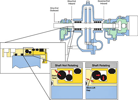
From their original industrial design in the late 1800s, small steam turbines have incorporated bushing-type single-piece and/or segmented multipiece carbon gland inserts (Image 1, top) to limit or throttle escaping steam.
Initially, simple deflectors or flinger discs were attached between the steam gland and adjacent bearing(s) in the expectation that steam leakage along the shaft would be reduced. However, turbine shafts are made from steel, and the steel’s coefficient of thermal expansion differs from that of carbon.
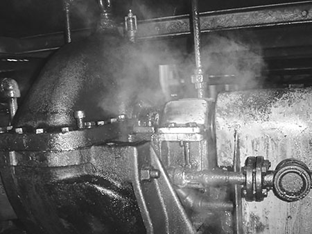
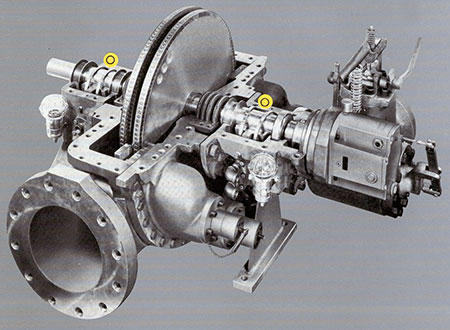
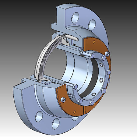
Thus, even with close-fitting segmented carbon rings, true leakage prevention has never been achieved. As a small amount of steam rushes through gaps at sonic velocity, an abrasive effect known as “steam cutting” continually erodes or widens the gap. The interacting processes of physics, thermodynamics and hydraulics combine to cause steam leakage, as seen in Image 2.
The need to limit steam egress through optimized steam gland selection becomes evident, and two design elements—steam glands and bearing housing protector (isolator) seals—contribute to the protection of bearings in small turbines. Together, they greatly enhance both steam gland effectiveness (saving steam) and bearing protection.
The drawbacks of segmented carbon gland inserts are discussed first. That small steam turbines (general purpose steam turbines), often suffer from steam leakage at both drive and governor-end sealing housings is widely known. Whenever these housings or glands incorporate the segmented carbon rings shown in Image 1, these segmented rings are prone to leak for the reasons stated above.
Reduced leakage is obtainable by allowing time for running-in and by applying timed start-stop-cool cycles that are linked to temperatures reached during successive cycles. The underlying science is linked to thermal expansion; carbon segments and steel shafts expand at much different rates.
Unless timed start-stop-cool cycles are observed during the typically eight-hour duration run-in cycle, the leakage gap will grow due to progressive erosion. So long as equipment owners take the time to monitor and implement proper run-in, segmented carbon rings may serve them well.
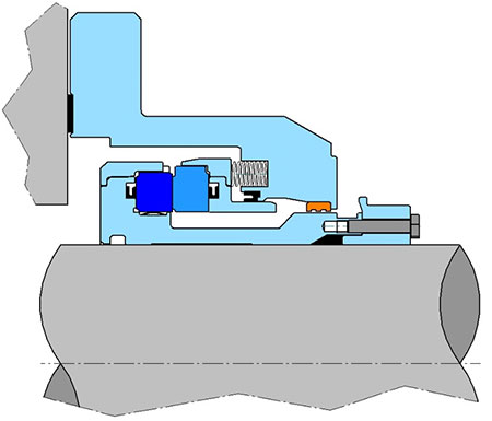
However, if a facility does not follow procedures or decides to entrust maintenance tasks to workers who disregard these requirements, repair frequencies and maintenance expenditures will increase. As an aside, keep in mind that upgrading the steam turbine shown in Image 3 would include replacing both of the unbalanced, constant level lubricators with a more modern, balanced version.
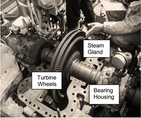
Each of the two bearing housings in Images 3 and 4 is located adjacent to one of the two steam glands; the ones shown in Image 3 contain four carbon rings. Whenever segmented carbon rings begin to wear, high-pressure and high-velocity leakage steam finds its way into the adjacent bearing housings.
Traditional labyrinth seals have proven ineffective in many such cases, and only seal glands incorporating either dry gas seal (DGS) or advanced high-temperature mechanical seal technology succeed in blocking the passage of leakage steam. However, for seal faces using DGS technology, the steam must be dry and clean.
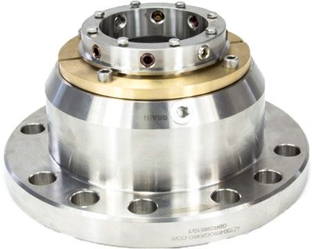
If pure steam is not available, seal face combinations using advanced mechanical seal know-how are preferred over face technology derived from DGS experience. The feasibility and cost-effectiveness of using bellows seals instead of segmented carbon inserts in small steam turbines was first established and reported in 19851 and predates DGS experience. Today, either DGS or bellows-type mechanical seals are mounted inside the cartridge shown in Image 5.
Returning to the subject of bearing housing protector seals, note that best-in-class (BiC) facilities have long recognized the difference between inexpensive rudimentary and advanced designs.
Advanced bearing protector seals are carefully engineered to curtail and even prevent contaminant ingress and oil leakage. Although inexpensive, the flying O-ring, which can have surface degradation when contacting an opposing sharp-edged stationary containment groove, and elastomeric lip seals may no longer be the best options for sealing at the bearing housing.
Regarding lip seals, it has been established that leak-free operation typically lasts about 2,000 hours, which is approximately three months. Also, when lip seals are too tight, they cause shaft wear. In some cases, lip seal and O-ring degradation can cause lubricant discoloration known as black oil.
Once lip seals have worn and can no longer seal tightly, steam, air, oil and other fluids are lost through leakage.
The inadequacies of lip seals are recognized by the American Petroleum Institute (API) 610 standard for process pumps. This widely accepted guideline document disallows lip seals and calls for either rotating labyrinth-style or contacting face seals.
Returning to the bearing housing protector seal in Image 6, this configuration was specifically designed for steam turbines.2 Material selection is governed by all applicable engineering principles. With modern steam glands as the primary shield against escaping steam, bearing housing protector seals can be viewed as a second line of defense.
Earlier versions of such seals incorporated a small and a large diameter dynamic O-ring. Both static and rotating components in the highly successful original protector seal assembly of Image 6 proved stable; the rotating component is not likely to wobble on the shaft and the entire seal is field-repairable.
At normal shaft rotational speeds, the smaller of the rotating (dynamic) O-rings is flung outward and away from the larger O-ring. The larger cross-section O-ring is then free to move axially and a micro-gap opens.
When the turbine is stopped, the outer of the two dynamic O-rings in Image 6 will move back to its stand-still location. At stand-still, the outer O-ring contracts and pushes the larger cross-section O-ring. In this purposeful design, the larger cross-section O-ring then touches a relatively large, contoured area. Because contact pressure equals force per unit area, a good design will aim for low pressure. In this protector seal design, the pressure is low because a large, well-contoured sealing area is present.
It should again be noted that today’s available designs differ from outdated configurations wherein contact with the sharp edges of an O-ring groove risked causing damage.
To restate: More recent single O-ring versions of this original design differ little from the original; single O-ring variants are both cost-effective and take up less space. As in the original design, once the turbine rotor reaches its operating speed, the O-ring moves diagonally outwards. This opens a microgap between the O-ring and a contoured seating surface, which will be contacted by the O-ring at standstill.
The need to keep airborne dust away from bearings is considerable in plants that process powdery substances. Although external air supplies are not normally needed, powder processing and many other applications benefit from an engineered air bleed variant.
Clean and dry instrument-grade air introduced (bled) into one of the small chambers of the bearing housing protector seal makes the air bleed variant an effective extender of lubricant and bearing life.
In summary: As of about 2017, many best-in-class facilities have discontinued using segmented carbon rings. The old-style steam glands shown in Image 4 (note one gland adjacent to each turbine wheel) would be replaced by the mechanical seat type steam gland cartridge illustrated in Image 5.
Different views of this steam gland cartridge are shown in Images 7 and 8. Adding state-of-art bearing housing protector seals contributes even more value to these upgrades.
References
1. Bloch, Heinz P., and Hurl Elliott; “Mechanical Seals for Medium-Pressure Steam Turbines,” presented at the ASLE 40th Annual Meeting in Las Vegas, NV, May 1985 and reprinted in Lubrication Engineering, November 1985
2. Bloch, Heinz P., “Fluid Machinery: Life Extension of Pumps, Gas Compressors, and Drivers;” (2020), DeGruyter Publishing, Berlin, Germany, ISBN 978-3-11-067413-2
