
Pumps & Systems, April 2013
Because of a skilled manpower shortage, particularly at remote sites, the industry has given less attention to the technical details of pump commissioning. A high percentage of pumps are commissioned and then improperly started. This can result in damages or unit production interruptions. Pump maintenance and repair can be costly, which makes pump pre-commissioning, commissioning and startup crucial in today’s industry.
Pump Alignment
Good pump alignment can provide improved bearing and seal life, lower vibration, superior pump reliability and better overall pump performance. Improper pump alignment can cause excessive vibration, premature wear and early failure. Adequate clearance for each pump casing is important for proper alignment. The pump shaft interface alignment tolerance should be around 0.0005 times the shaft diameter (approximately 0.01 to 0.02 millimeter for typical 25 to 50 millimeters shaft diameters). Some textbooks recommend alignment tolerance around 0.01 millimeter overall, regardless of the shaft diameter. Special pump trains may need tighter alignment tolerances.
Pump trains with flexible couplings (which transmit the torque through elastomeric materials) could tolerate interface fits higher than those mentioned. The coupling spacer length is also important because parallel misalignment accommodation is directly proportional to the length.
An important criterion for pump alignment is the pump’s running vibration. If excessive, particularly at twice the running speed (or axially), a further alignment improvement is required. The analysis of failed pump components—such as bearings, couplings and seals—can also indicate the need for improved alignment.
Commonly used alignment methods fall into three categories: reverse indicator, face and rim and face face distance.
The Reverse-Indicator Method
The reverse-indicator method preferred for modern pump alignment. The accuracy of this method cannot be affected by the axial movement of the shafts in sleeve bearings (used in large pumps). Both shafts should turn together (generally both shafts should be rotatable and coupled together). This prevents the coupling eccentricity or the surface irregularities from reducing the accuracy of the alignment readings. The geometrical accuracy is usually better using this method. It is convenient and generally implemented without disconnecting the coupling.
For complex alignment situations in which thermal growth or multi-casing pump trains are involved, the reverse-indicator method could be used. Usually a single-axis leveling is sufficient for pumps using rolling element bearings (small- and medium-size pumps), and a two-axis leveling could suffice for pumps employing sleeve bearings.
Some limitations exist when using the reverse-indicator alignment method. If the coupling diameter exceeds the available axial measurement span (closely-packaged pumps), the geometric accuracy may be poor using the reverse-indicator alignment method (compared to other methods). The general trend is toward high-torsional-stiffness couplings (such as metallic, flexible, spacer-type couplings).
.jpg)
Image 1. An example of a horizontal API pump at startup—this pump train uses a properly-spaced coupling.
The Face-and-Rim Method
The face-and-rim method, a traditional alignment procedure, was popular decades ago. It can be used on large and heavy pumps, those with shafts that cannot be turned. However, some run out error may occur because of the shaft or coupling eccentricity. It may offer a better geometric accuracy compared to the reverse-indicator alignment method for couplings with short spans (a small span-to-diameter ratio). Generally, this method is easier to apply on short coupling spans or small, non-critical pumps.
If this method is used on a large pump with sleeve bearings, the axial float error could be significant, and a special procedure may be required. As a general rule, two-axis leveling or three-axis leveling could be required for rolling element bearings and sleeve bearings, respectively (the reverse-indicator method requires leveling in one less axis for each).
For long spans, the face-and-rim method requires spacer removal to permit face mounting.
The Face-Face-Distance Method
The face-face-distance alignment method is used for long spans (such as special pump trains that use a long-transmission shaft instead of a coupling).
This method is usable without the elaborate long-span bracket or other special considerations. Its geometric accuracy is normally lower than the other methods. It has no advantage over other commonly-used alignment methods for anything except long spans (such as long connecting shafts).
Laser Optic Alignment
Laser optic alignment is common. Devices usually use a semiconductor emitting a laser beam in the infrared range (wavelengths around 800 millimeters) along with a beam-finder incorporating an infrared detector. Physical contact is not required since this is now bridged by a laser beam. Usual accuracy is one micron using modern laser optic alignment methods. With the data automatically obtained from sensor(s), the system can yield the horizontal and vertical adjustments required.
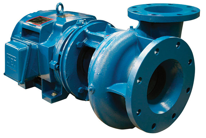
Image 2. An example of a closely-coupled horizontal ANSI pump.
Thermal growth (or pump contraction) can be significant for alignment purposes. The relative movement of one casing/machine compared to other(s) is a concern (absolute movements do not affect the alignment). Movements because of pipe loads, fluid forces and torque reactions have important effects. Pump vibration can indicate whether thermal movements and other operational effects are causing misalignment during startup or operation. Considering the thermal operational growth correction in the pump alignment may be required during commissioning. One of the best methods can be mechanical pump measurements during operation onsite with the final foundation and piping. Another recommendation is to make pump and piping adjustments during operation, using vibration as the primary reference.
Field Balancing
Unbalance occurs for many reasons—including distortion, deflection, dimensional changes and other problems. An improper shipment and poor assembly, installation and/or commissioning could result in rotating assembly unbalance.
Often, field balancing is required onsite during pump commissioning or startup. If the danger of this unbalance vibration is not recognized quickly, costly damages can occur. This may result in the destruction of bearings, seal damage, cracks in different components, foundation damage, mounting system problems or other issues.
With a simply supported rotor assembly (bearing at both ends), vibration because of unbalance will occur mainly in the radial plane. In the case of an over-hung rotor, high axial vibrations may also occur (the axial vibration amplitude may equal those measured radially). Field balancing of the pump rotor could be necessary to increase safety and bearing and seal life. It may also be needed to minimize the vibration (and stresses), noise, fatigue and power losses.
Four basic types of unbalance are:
- Static unbalance exists when the principal axis of inertia is displaced parallel to the shaft axis. This type of unbalance is found primarily in narrow, disc-shaped rotating parts, such as a thin pump impeller. Static balance is satisfactory only for relatively slow-revolving disc-shaped components or for parts that are subsequently assembled onto a larger rotor that is then balanced dynamically as an assembly.
- Couple unbalance occurs when two equal unbalance masses are positioned at opposite ends of a rotor and spaced 180 degrees from each other.
- Quasi-static unbalance represents the specific combination of static and couple unbalance in which the angular position of one coupled component coincides with the angular position of static unbalance.
Dynamic unbalance occurs when the central, principal axis of inertia is neither parallel to, nor intersects with, the shaft axis. It is the most common type unbalance and can only be corrected by mass correction in at least two planes perpendicular to the shaft axis.
A field balancing package usually provides sensing and monitoring instrumentation for the balancing of a pump rotor, while the rotor runs inside the pump, onsite (in its own bearings and under its own power). Field balancing systems consist of a combination of proper transducers and measurement devices that provide an unbalance indication proportional to the vibration magnitude. A suitable calculation module is used to convert the readings—usually the vibration in several runs with the test masses—into the magnitude and phase angle of the required correction masses. Vibration measurements at one end of a pump could be affected by an unbalance vibration from the other end. To accurately determine the size and phase angle of the needed correction masses, at least three runs are required. One is the current condition. The second uses a test mass in one plane. The third uses a test mass in another correction plane.
Lubrication System Commissioning
The cleanliness of a pump’s lubrication system is critical. The same oil as the specified operating lubrication oil should be used for the entire pump lubrication system flushing at the field. Any dirt or debris in a lubrication system should be collected in the lubrication filter (or additional strainers) during the flushing. Sufficient time is needed for the proper flushing of the lubrication circuits of a pump (usually one to two days).
The cleaning capacity of the lubrication oil is better at relatively high oil velocities, relatively high temperature and low viscosity. The transportation capacity of the lubrication oil is best when the oil is relatively thick at low temperature and high viscosity. The lubrication oil temperature should be varied within specified low and high limits, several times, for a proper lubrication system flushing.
Seal System Commissioning
During pump commissioning and startup, damages to mechanical seals often occur. Modern mechanical seals are usually supplied as a pre-mounted cartridge unit and often do not require adjustment during pump commissioning. Increased imperfections of concentricity and run-out in the pump shaft can lead to high vibrations, which significantly decrease the service life of the seal. The mechanical seal should be supplied with the required, clean seal fluid.
Startup Notes
When all accessories and utilities are ready, the pump can be started. The alignment should be monitored as the temperature changes to the operating level. Alignment changes should be properly documented, and the alignment should be corrected, if required. The pump’s operating data should be recorded on the job with liquid and stable operating conditions to establish the base reference points.
Operation & Maintenance Notes
For some pumps, tight manufacturing clearances and complex geometry make refurbishing difficult, especially when major damage occur or a catastrophic component fails (such as a bearing). The pump rotor may end up digging and melting into the casing. If bent, the rotor should be replaced. If not bent, it may be refurbished, which is usually a difficult process. For example, the rotor’s sealing edges can often be sprayed in case of damage. Repairing the pump casings could be both difficult and risky for machining and even more so for welding.
