

Performance matters when it comes to owning and operating a water system, and every component plays a part in delivering efficient, reliable operation. The key to maximizing performance is minimizing waste, sizing a system correctly and selecting components that make the most sense for the application.
Enter what is known as water-to-wire efficiency. With it, engineers can measure the efficiency of a pump and motor together, as well as the pipe, controls and wire necessary to complete the operation. In any business decision, oversizing leads to waste, and the same is true with a pumping system. By using water-to-wire efficiency measurements, engineers ensure they are picking the right size for every component in a system. The goal is to reduce the horsepower requirement while maximizing the pumping performance.
1. Determining Pump Efficiency
When considering a pump’s efficiency, engineers should look at two things: the pump’s label and the manufacturer’s pump curve.
In 2020, the U.S. Department of Energy started requiring all pump manufacturers to list the pump efficiency index (PEI) on a pump’s label alongside the pump family/model designation and the pump impeller diameter. These labels give users a clear method to compare the efficiency from one pump to another.

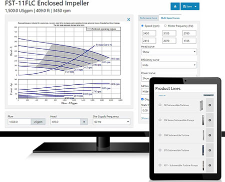
In addition to the pump label, pump manufacturers calculate a pump curve that shows the best efficiency point (BEP) for that pump. To properly size a pump, engineers need to consider the factors shown on the pump curve, including the total dynamic head and the desired flow rate in gallons per minute (gpm). Overestimating or underestimating the total dynamic head or the gpm needed to accomplish a job could have consequences for the optimization of a system. The pump curve maps out these efficiency points. The closer the pump’s BEP is to the desired conditions, the better. If the desired operating point is too far to the left of the BEP, motor power overload, high flow velocity wear, cavitation, higher-than-desired radial loads, shaft deflection, turbulence and erosion of the component parts of the pump could occur. Being too far to the right of the BEP could result in vibration, high temperature, excess recirculation, cavitation or extremely low efficiency. All of these can reduce the lifespan of the system.
2. Factoring Motor Designs
While motors offer clear horsepower ratings, it is important to look beyond these and consider motor materials and design. These factors can contribute significantly to performance. In fact, motor efficiency will vary between manufacturers based on construction materials and design. Generally, tighter manufacturing tolerances yield a more efficient product. A poor design will cause losses in heat and vibration, as well as poor energy conversion.
Like the pump efficiency standards, a manufacturer cannot simply place a sticker on a motor and say it is “premium efficient.” Independent trade organizations, like the National Electrical Manufacturers Association (NEMA) and the Hydraulic Institute, test and verify efficiencies claimed by manufacturers. Efficiency information for motors can be found on manufacturers’ websites as well as through the Hydraulic Institute.
Another consideration when selecting a motor is the motor’s technology. For example, submersible motors can employ highly efficient permanent magnet (PM) operation. PM motors are lighter and smaller than alternating current (AC) induction motors, and this can add to the ease of installation. PM motors do not have “slip” and operate at synchronous speeds. This often means getting more output when using a PM motor when compared to a typical three-phase induction motor. Users also have the benefit of possible energy savings of up to 20% compared to a standard induction. Since PM motors are generally more efficient and require less power than a comparable AC induction motor, systems can use smaller gauge wire for the same horsepower. This can equate to considerable cost savings for the wire. While the initial cost of these motors is higher than a traditional AC induction motor, the operational savings and wire savings can often overcome this.
3. Driving System Optimization With VFDs
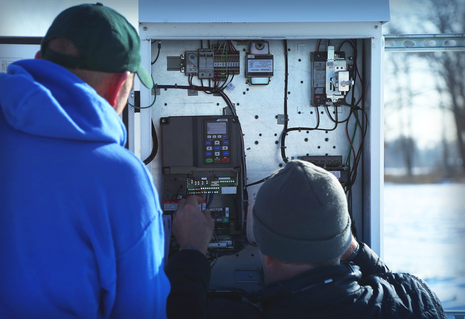
Another component that can maximize the efficiency of a pumping system is a variable frequency drive (VFD). With a VFD, users can regulate the system speed, providing precise adjustment of the flow and built-in motor protection based on motor current and temperature, as well as other inputs, depending on the options selected.
This ability to increase or decrease motor speed can deliver substantial efficiency benefits. If it is not always necessary for a pump to run at maximum flow, a VFD can be used to automatically reduce the speed. This can equate to considerable energy cost savings.

For example, if a user has a 10-horsepower motor and they reduce the speed from 1,800 rotations per minute (rpm) to 1,500 rpm (approximately 17% speed reduction), the horsepower requirement goes down to 5.78 horsepower. They are only using about half of the horsepower they have available, equating to energy savings. Here is another example of how those numbers add up, using a 100-horsepower motor:
- The average cost of operating a 100-horsepower system at full capacity is $100,300 (590,000 kilowatt-hours [kWh] x the U.S. average of $0.17 per kWh).
- Running the same motor/pump at a reduced speed using a VFD would cost about $39,100 (230,000 kWh).
- This equates to savings of $61,200 per year.
- Since the average cost of a 100- horsepower VFD package is about $25,000, the drive could potentially pay for itself in about six months.
4-6. How Wire, Tank & Piping Size Make a Big Difference
When choosing a system for optimum efficiency, engineers also want to consider components such as the tank size, wire size and piping.
A properly sized tank will mean fewer on/off cycles. A tank that is too small could cause the user to exceed the number of starts the motor is rated for. Overcycling of any system can lead to premature failure of one or more of the system components. Energy consumption is also a factor when it comes to excess starts and stops due to the inrush currents. This will add to overall energy usage.
The type of motor that is chosen will affect the wire requirements, efficiency and cost. If a user has a 15-horsepower single-phase motor with a 4 American wire gauge (AWG) wire, they can only run a maximum of 270 feet. If they need a longer run, they must increase the wire gauge size, significantly increasing their cost. As a comparison, when using a 15-horsepower three-phase induction motor with 4 AWG wire size, they can go up to 520 feet. By selecting a three-phase motor as opposed to a single-phase motor, the user can double the length that a particular wire gauge would be acceptable. (Refer to all local and National Electrical Code [NEC] requirements for the application.)
A proper pipe size is also an important part of the size and design of a system, and it can lead to a potential reduction in horsepower requirement. Using a 1.5-inch diameter polyvinyl chloride (PVC) pipe instead of a 1-inch pipe will decrease pipe friction losses and head by approximately 10 times. For a 20-gpm application, if a 1-inch schedule 80 PVC plastic pipe is being used, head loss for 100 feet is 31.26 feet. If the pipe size is increased to 1.5 inches—the head loss for the same 100 feet of pipe—the loss is only 3.51 feet.
By increasing the pipe size by just a half-inch in this example, head loss is being reduced by 10 times. This can drastically affect the pump size and horsepower that would be required for a pump application. Proper pipe sizing not only improves the performance point on the curve but can also change the horsepower of the pump needed to improve electrical consumption and be more efficient for the overall system.
Maximizing System Reliability & Budget
Owners often wonder if a more efficient system is worth the cost. If a recommended operating system falls outside of a user’s budget, efficiency ratings can help justify the long-term cost benefits of additional upfront expenditures. These measurements can assess how the initial investment can lead to better performance, less downtime and less money spent on operating costs. In some cases, spending a little more upfront can save owners and operators time and money in the long run.
