

 IMAGE 1: Plumbing fixture unit values (Image courtesy of Zoeller)
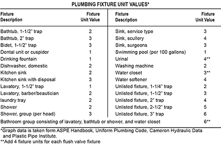
Sizing a pump, in many cases, is an afterthought. Many installers have a go-to pump that has been used for decades without fail. Then it happens: After finishing up an installation, the pump is tested to ensure a job well done … and nothing happens. The pump is running, but the water level is not moving. Why?
In pump sizing, two factors are needed to select a pump: flow and pressure. Flow is generally measured in gallons per minute (gpm). The max instantaneous flow that will be entering the pump’s basin needs to be determined so that a pump can be selected to efficiently maintain the system. Ideally, the design flow will be provided by a contractor, engineer or regulating authority, though there are several methods for estimating flow. For sewage applications, the fixture unit method is generally used. This method assigns a value to plumbing fixtures or a group of fixtures. Image 1 gives the units for various types of fixtures. First, determine the type and number of plumbing fixtures from where the pump will receive water. Next, convert all the plumbing fixtures to their respective number of fixture units. Then, add them together to get the total fixture units. To convert the fixture units to a flow rate, use a pump capacity versus fixture unit graph similar to Image 4. This will give the design flow rate that will be used to select a pump.
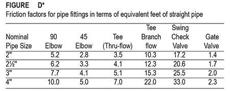 IMAGE 2: Equivalent length of fittings. Example: Image 6 has one check valve, one 90-degree elbow, two 45-degree elbows, one gate valve, and one branch flow tee for a total length of fittings of 39.7 feet.
The second piece needed is the pressure required to move the design flow rate through the system. This pressure is commonly referred to as total dynamic head (TDH). The unit commonly used to measure TDH is feet of water. As a reference, one psi is equal to 2.31 feet of water. In many cases, the TDH is the one variable that can change significantly from application to application depending on the site characteristics and requirements. Typically, there are two pieces whose sum make up total dynamic head: static head and friction head.
Static head is the vertical difference between the pump’s off point and the outfall of the system. Be sure to check for any high points between the pump and outfall. If there is a high point, it may be necessary to calculate the TDH from the pump to the high point and from the pump to the outfall and select a pump that will operate at both points. To be conservative, calculate static head by subtracting the pump off elevation from the highest elevation. The example in Image 6 has a static head of 10 feet.
When water flows through a pipe, there is frictional resistance between the water and the pipe wall which creates back pressure on the pump. Several factors affect friction loss: flow rate, pipe diameter, pipe material, pressure rating, length of pipe, age of the pipe, as well as the type and number of fittings. In order to properly size a pump, the friction loss needs to be determined at the design flow rate while taking the various factors into consideration.
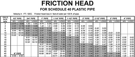 IMAGE 3: Friction loss table. Example: 40 gpm through a 2-inch SCH 40 pipe will have 2.64 feet of friction loss for every 100 feet of pipe and will produce a velocity of 3.82 feet per second (ft/s).
The first piece of determining friction loss is determining the total equivalent length of pipe. Calculating friction loss through a fitting can be difficult and cumbersome. Friction loss varies from fitting to fitting, so rather than calculating the friction loss through each fitting, Image 2 can be used to convert them to an equivalent length of straight pipe. This reduces the number of variables when calculating friction loss.
For example, the friction loss through a single, 2-inch, 90-degree elbow is equivalent to the friction loss through 5.2 feet of straight, 2-inch pipe. To calculate the total equivalent length of the system, convert each fitting to a straight length of pipe and add the equivalent length of all fittings to the nominal length of pipe. Image 6 has 250 feet of nominal pipe and 39.7 feet of equivalent fittings for a total equivalent length of 289.7 feet.
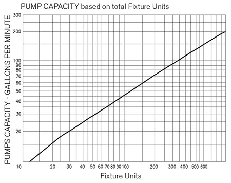 IMAGE 4: Pump capacity versus fixture units
To further simplify calculating friction loss, use a friction loss table like Image 3. Be sure the friction loss table is for the same type and pressure-rated pipe that is installed. This table is used to determine the friction loss per 100 feet of pipe. Simply find the diameter of the pipe along the top row and trace it down to the design flow rate. The value in the loss column provides the friction loss factor at a given flow rate. To calculate friction loss, divide the total length of pipe by 100 and multiply it by the friction loss factor. For example, 40 gpm through 290 feet of 2-inch pipe will result in a friction loss of 7.7 feet of water (290÷100*2.64). Then add the friction loss to the static head to determine the TDH. The example in Image 6 will have a TDH of 17.7 feet of water at 40 gpm.
The design flow and TDH together provide a design point that is used to select a pump. The design point must be on or inside the pump’s performance curve. If the design point is above or to the right of the performance curve, the pump will not be able to meet the design flow which may lead to nuisance alarms, overflow or premature failure. In general, it is best to select a pump closest to the design point and to which the design point is near the center of the curve.
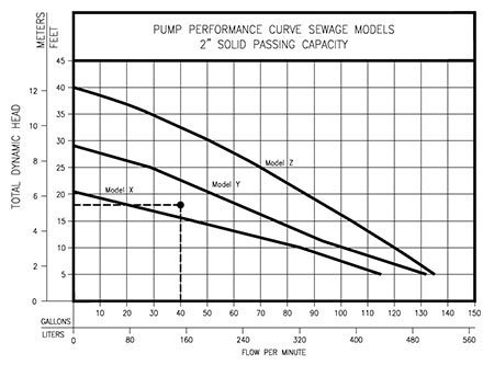 IMAGE 5: Design point plotted against a group of performance curves
Following along with the example, the design flow is 40 gpm with a total dynamic head of 17.7 feet. To plot the design point, draw a line at 40 gpm and 18 feet TDH—where the two lines meet is the design point. Model X will not be able to produce 40 gpm at 18 feet TDH and, therefore, is not a suitable pump. Model Z will meet the minimum requirements, but it will produce more flow than is necessary. Model Y can meet the minimum requirements and is closest to the design point. Therefore, it is the best fit for this example.
Another key factor when sizing pumps in the wastewater industry is water velocity. When the pump shuts off and the water stops flowing, the solids can begin to settle in the pipe. It is important to ensure there is enough flow, and subsequently enough velocity, to resuspend the solids to prevent buildup or clogging. To prevent solids from settling, the pump needs to be able to produce a minimum scouring velocity of 2 feet per second (ft/s), though 3 to 5 ft/s is preferred. Use a friction loss table similar to Image 3 that provides the velocity under the VEL column. If the velocity is lower than 2 ft/s, consider reducing the pipe diameter or increasing the design flow.
In some instances, there are additional pressure requirements that may affect the TDH calculation. Typical applications that have additional requirements are low-pressure distribution systems, sprinkler systems, multiple pumps on a common force main or any application that has a pressure requirement other than static or friction head. Additional pressure requirements are not addressed in this article. If a system has additional pressure requirements, reach out to the manufacturer or local rep for assistance in sizing a pump.
Ultimately, the most important aspect of pump sizing is gathering accurate and complete information for each project.
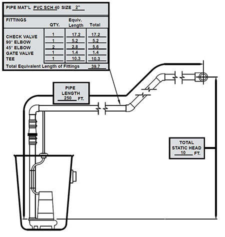 IMAGE 6: Sewage lift station example
The following questions can be used as a reference for collecting project information needed to size a pump.
1. What are the electrical conditions?
This does not affect the hydraulics or pump sizing, but the voltage and phase of the motor have to match the service voltage available at the site and an electrician needs to confirm the circuit is properly sized.
2. Is this a residential, commercial or municipal application?
This is needed to ensure an appropriately economical solution is provided. A residential pump does not need the same upgrades that a municipal or commercial pump may need.
3. What type of fluid is being pumped? Sewage, effluent, groundwater or some other liquid?
Be sure to select a pump that is designed to operate in the given environment.
4. What is the design flow?
The fixture unit method is not always the best method to determine flow for larger, commercial or municipal applications. Check with the customer, engineer or the local regulating authority on how to determine the flow if not provided.
5. What is the static head?
This is a critical component in determining the TDH.
6. How far is the water being pumped?
A critical component to determine the total equivalent length for the friction loss calculation.
7. What diameter and type of pipe is being used?
Friction loss differs based on the material and inside diameter of the pipe. Be sure to use the correct corresponding friction loss table.
8. What type and number of fittings are included?
Used to determine the total equivalent length for the friction loss calculation
9. Where is the water being pumped? Is the water being pumped to a gravity sewer, septic tank, pressurized system, etc.?
Additional pressure requirements will need to be accounted for in the pump sizing—contact the manufacturer or local rep for assistance.
