

There are many different types of equipment that require sealing a rotating shaft passing through a stationary housing. Two common examples are pumps and mixers (or agitators). While the basic principles of sealing different equipment are similar, there are distinctions that require different solutions. This misunderstanding has led to conflicts such as invoking American Petroleum Institute (API) 682 (a pump mechanical seal standard) when specifying seals for mixers.
When considering mechanical seals for pumps versus mixers, there are a few obvious differences between the two categories. For instance, overhung pumps have shorter distances (typically measured in inches) from the impeller to the radial bearing when compared to a typical top entry mixer (typically measured in feet). This long unsupported distance results in a less stable platform with greater radial runout, perpendicular misalignment and eccentricity than pumps. The increased equipment runout poses some design challenges for mechanical seals.
Equation 1
δ = [(Ft * Lm) / (6 * Ey * I)] *
[(2 * Li * Lb) + (3 * Li * Lm) + Lm2]
Where:
Ft = load acting on the impeller
Li = length from the lower gear box bearing to the impeller
Lm = length from the lower gear box bearing to the seal mounting surface
Lb = length between gear box
bearings
I = shaft moment of inertia
Ey = shaft modulus of elasticity
What if the deflection of the shaft was purely radial? Designing a seal for this condition could be accomplished easily by increasing clearances between rotating and stationary components along with widening seal face running surfaces. As suspected, the issues are not this simple. Side loading on the impeller(s), wherever they lie on the mixer shaft, imparts a deflection that translates all the way through the seal to the first point of shaft support—the gearbox radial bearing. Because of shaft deflection along with pendulum motion, the deflection is not a linear function. This will have a radial and an angular component to it that creates a perpendicular misalignment at the seal that can cause problems for the mechanical seal. The deflection can be calculated if key attributes of the shaft and shaft loading are known.
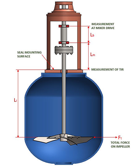
For example, API 682 states that the shaft radial deflection at the seal faces of a pump should be equal to or less than 0.002 inches total indicated reading (TIR) at the most severe conditions. Normal ranges on a top entry mixer are between 0.03 to 0.150 inches TIR. Problems within the mechanical seal that can occur due to excessive shaft deflection include increased wear to the seal components, rotating components contacting/damaging stationary components, rolling and pinching of the dynamic O-ring (causing spiral failure of the O-ring or face hang up). These can all lead to reduced seal life. Because of the excessive motion inherent in mixers, mechanical seals can exhibit more leakage as compared to similar pump seals, which can lead to the seal being pulled unnecessarily and/or even premature failures if not monitored closely. There are instances when working closely with equipment manufacturers and understanding the design of the equipment where a rolling element bearing can be incorporated into seal cartridges to limit the angularity at the seal faces and mitigate these problems. Care must be taken to implement the proper type of bearing and that the potential bearing loads are completely understood or the problem could get worse or even create a new problem, with the addition of a bearing. Seal vendors should work closely with the OEM and bearing manufacturers to ensure proper design.
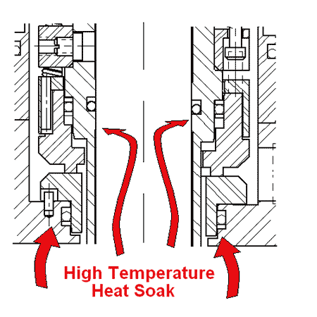
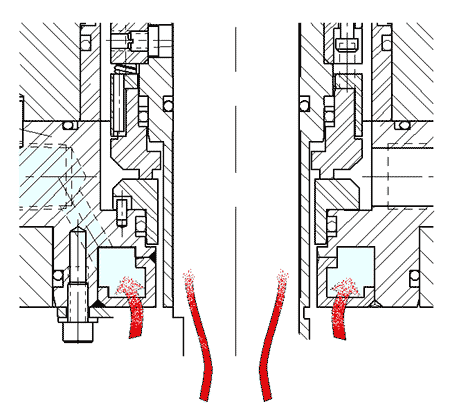
IMAGE 2: A properly designed cooling spool can prevent excessive temperatures that can result in damage.
Mixer seal applications are typically low speed (5 to 300 rotations per minute [rpm]) and cannot use some traditional methods to keep barrier fluids cool. For example, in a Plan 53A for dual seals, barrier fluid circulation is provided by an internal pumping feature like an axial pumping screw. The challenge is the pumping feature relies on equipment speed to generate flow and typical mixing speeds are not high enough to generate useful flow rates. The good news is that seal face generated heat is not generally what causes the barrier fluid temperature to rise in a mixer seal. It is heat soak from the process that can cause increased barrier fluid temperatures as well as making lower seal components, faces and elastomers, for example, vulnerable to high temperatures.
The lower seal components, such as seal faces and O-rings, are more vulnerable due to proximity to the process. It is not the heat that directly damages seal faces but rather the reduced viscosity and, therefore, lubricity of the barrier fluid at the lower seal faces. Poor lubrication causes face damage due to contact. Other design features can be incorporated into the seal cartridge to keep barrier temperatures low and protect seal components.
Mechanical seals for mixers can be designed with internal cooling coils or jackets that are in direct contact with barrier fluid. These features are a closed-loop, low-pressure, low-flow system that has cooling water circulated through them acting as an integral heat exchanger.
Another method is to use a cooling spool in the seal cartridge between the lower seal components and equipment mounting surface. A cooling spool is a cavity that low-pressure cooling water can flow through to create an insulating barrier between the seal and vessel to limit heat soak. A properly designed cooling spool can prevent excessive temperatures that can result in damage of seal faces and elastomers. Heat soak from the process causes barrier fluid temperature to rise instead. These two design features can be used in conjunction or individually to help control the temperatures at the mechanical seal.
Quite often, mechanical seals for mixers are specified to comply with API 682, 4th Edition Category 1, even though these machines do not comply with the design requirements in API 610/682 functionally, dimensionally and/or mechanically. This may be because end users are familiar with and comfortable with API 682 as a seal specification and are not aware of some of the industry specifications that are more applicable for these machines/seals.
Process Industry Practices (PIP) and Deutsches Institut fur Normung (DIN) are two industry standards that are more appropriate for these types of seals—DIN 28138/28154 standards have long been specified for mixer OEMs in Europe, and PIP RESM003 has become used as a specification requirement for mechanical seals on mixing equipment. Outside of these specifications, there are no commonly practiced industry standards, which leads to a wide variety of seal chamber dimensions, machining tolerances, shaft deflection, gearbox designs, bearing arrangements, etc., which varies from OEM to OEM. The user’s location and industry will largely determine which one of these specifications would be most appropriate for their site mixer mechanical seals.
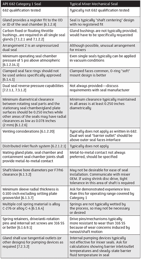
Specifying API 682 for a mixer seal may be an unnecessary added expense and complication. While is it possible to incorporate an API 682-qualified basic seal into a mixer configuration, this approach commonly results in compromise both in terms of the compliance to API 682 as well as in the suitability of the design for mixer applications. Image 3 shows a list of differences between an API 682 Category 1 seal versus a typical mixer mechanical seal.
