

Part 1 of this three-part column ran in the February issue of Pumps & Systems and can be found here. Look for Part 3 in next month’s issue.
Pipe Material & Schedule
Now that you know the nominal pipe size for your system, what material and schedule are you going to use? I actually do not have a lot to say on this subject because it seems that most people make these decisions correctly. The properties of the liquid will dictate the correct material selection. Expected pressure ranges will dictate the schedule (wall thickness) of the pipe. Different pipe schedules, materials and age will alter the friction characteristics of the system. So, be sure to use the actual internal diameter of the pipe and compensate for added friction over time.
Pipe Expansion & Contraction
If your system is located where the ambient temperature never changes (San Diego, California or Loja, Ecuador) and the system process temperature remains constant, then there is little to no issue. Most systems, however, do experience expansion and contraction even if it is just due to the difference in day and night temperatures or if the process duty cycle is a lot of on-and-off.
Metallic pipe expands and contracts in the normal course of operation due to temperature changes in the ambient and the process. When the pipe heats up, it obviously expands and, of course, that expansion force (stress/strain) has to go somewhere. If not properly compensated/anchored, the expansion can create detrimental issues leading to total failure of the pump and system. As an example: An unrestrained 6-inch carbon steel pipe that is 100 feet long when raised in temperature by 200 F from ambient would expand 1.5 inches and can easily result in a force of over 34,000 pounds per square inch (psi) or about 17.4 tons.
Expansion joints installed in the pipe can solve and create pipe system problems. If the joint is not properly anchored or contained, the large forces can be transmitted directly to the pump flange. The expansion joint, acting as a bellows, expands under the pressure and the resultant force causes both ends of the pipe where it is attached to move apart with great force. The magnitude of the force can be calculated simply as F = A x P—where F is the resultant force, A is the area of the expansion joint, and P is the discharge pressure of the pump. For example, an expansion joint in an 8-inch pipe at a pressure of 100 psi would yield a force of a little over 5,000 psi or 2.5 tons of force. Most pumps are not going to react well to an added 2.5 tons of force on the nozzle. It is imperative that the expansion joint is anchored so the force is transmitted away from the piping system and the pump.
All piping should be independently supported and make sure to also include the liquid weight in the calculations. Pumps are ultrasensitive to all the moments and forces exerted on them by the piping. Excess force on the pump will manifest as short-lived bearing and mechanical seal life and, at the higher levels, as broken flanges and seized rotors.
All piping should be anchored at key points, but there is a significant difference between a pipe support and a pipe anchor. An anchor point provides axial restraint while a pipe support does not. Most importantly, please know that a pump is not to be used as an anchor point or a support. As one of my old mentors used to joke, “The pump is the most expensive pipe support you can buy.”
Remember
Pumps in the field that ostensibly don’t meet the published performance curve parameters can almost always have their performance improved by adding some length of straight pipe on the suction side.
Pump Suction
Most pump system problems occur on the suction side of the pump (my personal estimate is over 85%). Improperly designed suction side systems probably account for almost all pump problems. If you are a regular reader of my columns, you already know to debunk the common misconceptions. You also know that the pump cannot reach out and pull, nor can it suck, the liquid into the eye of the impeller; further, the liquid has no tensile strength, so it cannot be pulled in. It is the function and responsibility of the suction system to deliver the liquid to the pump.
Best practice is to keep the suction pipe as short and as unobstructed as possible. Design so that net positive suction head available (NPSHa) is as high as possible, but at the same time also present the liquid’s best symmetric velocity profile.
Give it to Me Straight, Doc
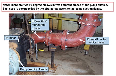
For more than 100 years, pump manufacturers have asked (begged) for 5 to 10 diameters of straight, unobstructed piping on the suction side of the pump. Ten diameters means that for a 6-inch diameter pipe the straight run would be 60 inches (10 x 6 = 60). Unobstructed means no elbows, no valves, no strainers/filters, no “tees” and no anything.
This suggestion/request/recommendation for 5 to 10 diameters of unobstructed piping on the pump suction is rarely conceded in the brutal and fast-paced reality of construction sites. For numerous reasons—including general cost due to geometric footprint specified restrictions, space available and ignorance—the 5 to 10 diameter request is typically discounted, ignored and neglected in the chaos and confusion of the project.
I will concede that not all pump applications actually require the 5 to 10 diameter unobstructed suction line rule. I would be very happy in most cases with 3 to 5. The higher the pump suction energy in conjunction with the amount of pre-swirl/pre-rotation, the more it is required (refer to my May 2020 column on this subject on high energy suction conditions).
If you have an ambient temperature water transfer pump that is less than 5 brake horsepower (BHP) and operates a few hours a week, then the rule would be overkill. As you move up on the suction energy level scale along with increased duty cycle, the more the rule becomes valid. Also, the higher the suction side liquid velocity, the more the rule is needed. It would be difficult to offer an accurate general rule for best solutions in this scenario. Just know, in general, the higher the flow rate, the higher the BHP, and the higher the liquid velocity, then the more the 10 diameter rule applies. Some assistance for answering these questions is offered in ANSI/HI 9.6.6–2016.
Why 10 diameters of straight pipe? The simple explanation is to deliver a symmetrically balanced velocity profile—a full 360 degrees of equal and laminar flow presented to the eye of the pump impeller. If the flow profile is not balanced, it will place an unequal radial and axial force/stress on the impeller that translates via the shaft to the bearings and mechanical seal. The asymmetrical velocity profile also prevents the impeller from doing its work at full design efficiency. The goal is to remove the uneven and often swirling corkscrew-shaped velocity profile and instead present a nice, symmetrical pressure and velocity balanced profile to the impeller.
As a general rule, it is an industry best practice to keep the suction line liquid velocities below 6 feet per second (1.8 meters per second), and surely below 10 feet per second (3 meters per second). Note that the Hydraulic Institute recommends 8 feet per second (2.4 meters per second) as a maximum for nonslurry applications. There are numerous successful installations with much higher suction velocities, but I also note that almost every installation I encounter with system issues has high suction velocities.
In the final approach to the pump suction (the last 5 to 10 diameters of pipe), which should be both straight and unobstructed, it is understood that the corresponding liquid velocity will be higher than the above recommendations; this is expected because this pipe section will be the same diameter as the pump suction. The compromise for this short section only is to trade the velocity restriction for a symmetrical velocity profile. It is also conceded that the added friction can be a detriment to the critical value of NPSHa.
References
1. Rotodynamic Pumps for Pump Piping ANSI/HI 9.6.6 2016
2. Centrifugal Pump Users Guidebook (Problems and Solutions) by Sam Yedidiah
3. Pump Handbook 4th edition by Paul Cooper, Igor Karassik, et al
4. Institute for Pumps and Mechanical Seals by William (Bill) J. McNally (SS)
5. Review pump suction reducer selection…, Vol 56 No. 3 October 2014 of Journal of South African Institution of Civil Engineering,by Ross Mahaffey (PE) and S.J. Van Vuuren (PE)
Read more Common Pumping Mistakes articles here.
