
How this practice can affect pump efficiency, NPSHr, axial vibration and more.
Turbomachinery Consultant
12/27/2018
 The cover of the first ever issue of Pumps & Systems, published in January 1993.
When trimming a pump impeller to change the flow and head, I sometimes get too much of a reduction. What is the problem?
With a constant rotational speed, as is the case with most pumps, the “Affinity Laws” commonly used for calculating the trim do not accurately reflect the relationship between the change in impeller diameter and the hydraulic performance achieved by the pump. The calculations generally dictate more of a cut than required to affect the desired head and flow reduction. If the calculated trimming calls for a 10 percent reduction in diameter, only a 7 or 8 percent reduction should be made. The lower the specific speed of the impeller design and the larger the discrepancy. This subject is covered in only a few pump handbooks. The subject is well covered on pages 18 and 19 of Centrifugal Pumps – Design and Application, First Edition, by Val Labanoff and Robert R. Ross.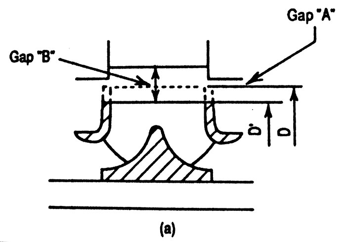 Image 1. Shroud and vane reduction (Images courtesy of the author)
- The “Affinity Laws” assume that the impeller shrouds are parallel. In actuality, the shrouds are parallel only in lower specific speed pumps.
- The liquid exit angle is altered as the impeller is trimmed, so the head curve steepens slightly.
- There is increased turbulent flow at the vane-tips as the impeller is trimmed, if the shroud-to-casing clearance is not maintained.
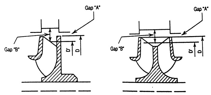 Image 2. Oblique cuts of vanes
What is the effect of trimming an impeller on pump efficiency?
It depends on the specific speed of the impeller. The specific speed index classifies the hydraulic features of pump impellers according to their type and proportions. Most refinery pumps fall between about 900 and 2,500 on this index. Some vertical multistage pumps are in the 4,000 to 6,000 range. For radial designs, impeller diameter should not be reduced more than 70 percent of the maximum diameter design. Reductions in pump impeller diameters also alter outlet channel width, blade exit angle and blade length and may significantly reduce the efficiency. The greater the impeller diameter reduction from maximum diameter and the higher the specific speed (not suction specific speed), the more the pump efficiency will decrease with the trimming of the impeller.What is the effect of impeller trimming on net positive suction head required (NPSHr)?
Small reductions in impeller diameter will increase NPSH only slightly. Diameter reductions greater than about 5 to 10 percent will increase NPSHr, which occurs because specific vane loading is raised by the reduced vane length, affecting velocity distribution at the impeller inlet. Not all pump companies consistently show on their pump curves the increase NPSHr with reduced impeller diameters. Attention must be paid to this factor when the margin between NPSHr and NPSH available (NPSHa) is very narrow or the NPSHr for a pump is extremely low.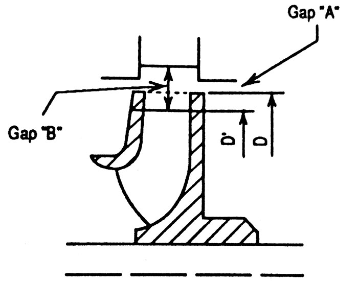 Image 3. Terminating vanes only
What effect does trimming an impeller have on axial vibration?
Excessive impeller shroud-to-casing clearances and suction recirculation cause eddy flows around the impeller, which in turn cause low frequency axial vibrations. Flow disturbances related to suction recirculation and cavitation are always present in both diffuser and volute type pumps. As the impeller diameters are reduced, the flow distribution pattern across the exit width of the impeller becomes more unstable. The tendency for the high-pressure liquid to return to the low pressure side and create tip recirculation is greatly increased. Again, the higher energy level pumps are of major concern—above 200 horsepower (hp) and 650 feet of head per stage.What are the effects of trimming an impeller on radial vibration?
Careful machining of the volute or diffuser tips to increase Gap B while maintaining Gap A has been used for a number of years to greatly reduce the vane-passing frequency vibration. The pulsating hydraulic forces acting on the impeller can be reduced by 80 to 85 percent by increasing the radial Gap B from 1 to 6 percent.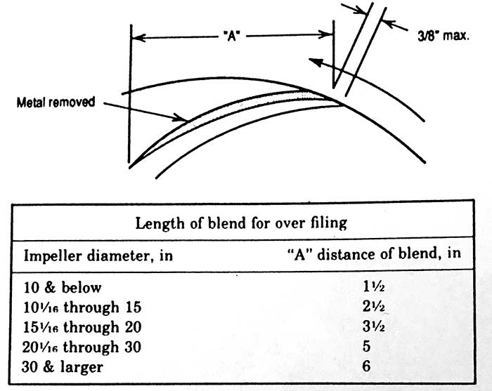 Image 4. Impeller vane overfiling
 Table 1. Recommended radial gaps for pumps
When trimming an impeller from its maximum diameter to adjust the head and flow developed by a centrifugal pump, what is the best way to cut the impeller? Is it best to trim the impeller vanes and the shrouds or just the vanes?
No hard and fast guidelines for the mechanical aspects of impeller trimming exist, but there are several pump construction and hydraulic design factors to consider while making the decision of what to trim. How the impeller is trimmed will greatly influence the hydraulic performance of the pump as well as the vibration levels experienced. Evaluate the hydraulic characteristics before you decide how to trim the impeller. For volute type pumps, the entire impeller, vanes and shrouds may be cut as shown in Image 1. However, in some pumps, this method will alter Gap A (shroud-to-case clearance), leading to uneven flow distribution at the impeller exit area, which can cause axial vibration and other problems. The double suction impeller type pump is especially sensitive to problems caused by increasing Gap A, so trimming the entire impeller is not a good choice. It is best to cut the impeller vanes obliquely (Image 2), which leaves the shrouds unchanged, or cut the vanes only (Image 3). Trimming the vanes only tends to even out the exit flow pattern and reduce recirculation tendencies at the exit area. Gap A should be about 0.050 inch (radial) for minimum vibration due to vane-passing frequency. In most diffuser type pumps, it is best to trim only the vanes (Image 3) to control tip recirculation and the ill effects of an increased Gap A. This cut yields a more stable head curve. The uniform flow reduces the tendency for tip recirculation and the possibility of suction recirculation is greatly reduced at the exit area. Structural strength of the shrouds is a factor in the decision in how to trim the impeller. There may be too much unsupported shroud left after a major reduction in diameter. The oblique cut leaves the shrouds unchanged and solves the structural strength problem and improves the exit flow pattern.I frequently encounter “vane-passing” frequencies during vibration analysis of a pump. What are some of the methods that can be used to reduce this problem?
The most effective method of reducing vane-passing frequencies is carefully maintaining proper Gap A and Gap B clearances to reduce impeller-casing interaction. Sometimes, impellers manufactured with blunt vane tips cause disturbances in the impeller exit area and in the volute area by generating hydraulic “hammer” even when the impeller outside diameter is the correct distance from the cut water (Gap B).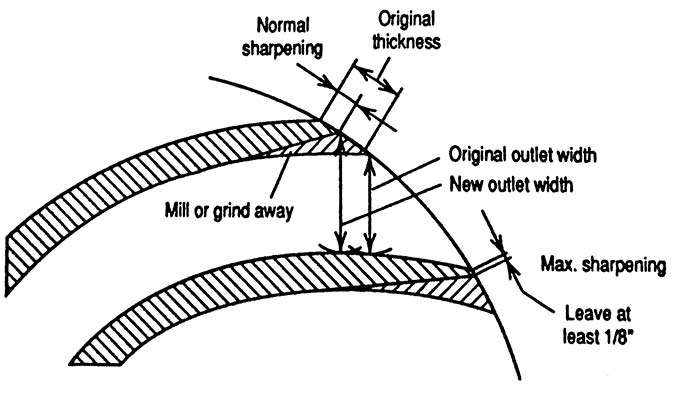 Image 5. Sharpening of impeller vanes