
Editor’s Note: As part of our ongoing series for our 25th anniversary year, this article published in January 1993 and written by James Netzel and Jon Hamaker of John Crane Inc., explained new technology to predict seal performance and improve design. Following the short excerpt below is a new article from the same company highlighting how computer aided engineering (CAE) is helping mechanical seals today.
Today’s sophisticated CAE tools are spearheading advanced equipment sealing technologies to promote safety and environmental protection, to ensure productivity and equipment reliability. Custom-developed CAE programs and state-of-the-art procedures are combining with essential experience and production/application expertise to provide better problem-solving seal designs for centrifugal pumps and faster, more accurate projections of seal performance. These new computer tools are used in all aspects of modern seal technology:
Information developed from these programs ensures compliance to the most stringent environmental regulations, before a pump and seal are put into service.
Mechanical seals and mechanical seal technologies have evolved significantly since their inception in the mid-1930s. With the growing demand in a variety of challenging applications, there is a need for advancing computational technologies that are capable of analyzing critical applications and special designs. Technology development within and throughout the industry has had a positive impact on optimizing seal products. Some products that were designed using traditional computer aided engineering (CAE) tools are still running successfully in the field after more than 25 years, validating the technology behind CAE tools.
Mechanical Seal Analysis
Finite element analysis (FEA) and computational fluid dynamics (CFD) tools are used to predict mechanical seal performance at operating conditions. Conventional engineering methods are complemented by these advanced computer-based simulation programs, allowing engineers to simulate the performance of mechanical seals under specific service conditions (see Image 1, page 96). When process upset conditions such as elevated pressures, temperatures or poor lubrication are encountered, excessive wear and leakage can result in reduced life or premature failure of the mechanical seal. Good practice dictates a seal to be analyzed at its true operating conditions using advanced mechanical seal modeling software. Some of the performance benefits of using these analytical tools are: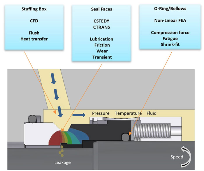 Image 1. Typical analysis tools (Images courtesy of John Crane)
- product optimization and increasing seal reliability
- increasing operating envelope
- reducing leakage of volatile organic compounds
- (VOC) emissions
- troubleshooting in-field problems
- reducing development time and costs on new product development projects
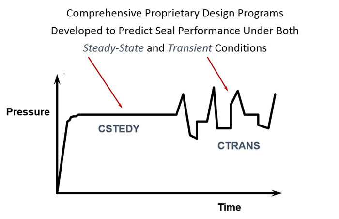 Image 2. Finite element-based computer programs that analyze operation and performance
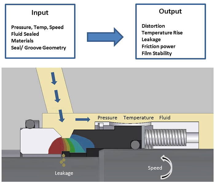 Image 3. Analytical tools
Special Sealing Solutions
HF Applications For certain applications, safety and reliability is of paramount concern. Pumps used in hydrofluoric (HF) acid alkylation units require a dual sealing system to minimize emissions. The use of a single cartridge mechanical seal in this hazardous service is not desirable, since any significant leakage past the inboard seal face could result in release of HF acid to the atmosphere. One option is to use a mechanical seal design that incorporates a wet contacting seal as the primary seal, a noncontacting outward pumping gas seal as the secondary seal and the segmented carbon bushing sealing between the outboard seal and the atmosphere. The recommended American Petroleum Institute (API) flush plan for this seal support system is API Plan 32/72/76. The primary seal uses a compatible clean flush media (Plan 32) of either isobutane or propane. The secondary seal is supported by a low-pressure purge of nitrogen (Plan 72) with the primary seal leakage vented to flare (Plan 76). The secondary seal face uses spiral groove technology, which is optimized by using the finite element-based computer program for steady state conditions. The result is a unique sealing solution made possible by the use of an advanced analytical software. The noncontacting seal face grooves are designed to pump from the inner diameter to the outer diameter a small amount of nitrogen leakage into the flare system. Vapor leakage past the inboard seal is isolated by the nitrogen quench seal and all emissions are directed to the flare system, essentially eliminating toxic emissions to the atmosphere. The spiral groove face seals operate using fluid mechanic principles. As the seal rotates, gas flows into the spiral grooves through a viscous shearing action and is compressed. At the sealing dam, gas is expanded. The combined film pressure results in an opening force greater than the closing force that separates the faces a few hundred microinches (see Image 4). The finite element-based computer program for steady state conditions was used to determine the number of grooves, groove depth, dam width fraction of face and spiral groove angle to predict optimum seal performance while ensuring outward pumping of dry nitrogen against the maximum flare pressure.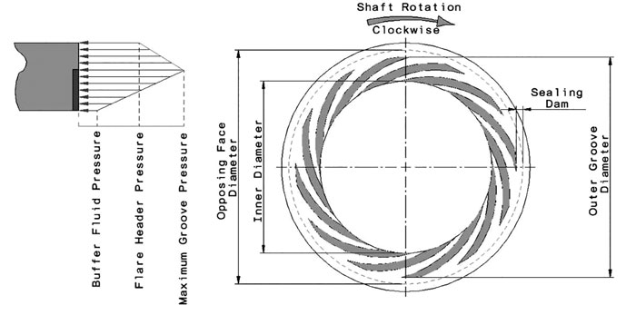 Image 4. Spiral groove face and pressure profile
Light Hydrocarbons
Sealing light hydrocarbons (specific gravity from 0.4 to 0.6) requires improved seal technology and tools to predict performance to meet the required VOC emission regulations. With a single seal configuration, plain faces in light hydrocarbon liquids can flash to a vapor. Though there is a sufficient vapor margin, the frictional heat generated at the face vaporizes the liquid causing the face to run dry and fail. In many pipeline duties, typical light hydrocarbon process fluids include butane, propane, Y-grade natural gas liquids (NGL), pentane and ethane-propane mixtures with seal chamber pressures usually in excess of 500 pounds per square inch (psi) (34.5 bar). Most pumps are on variable speed drives. Operation typically involves pumps oriented in series where speed is slowed due to downstream demand while suction pressures remain constant.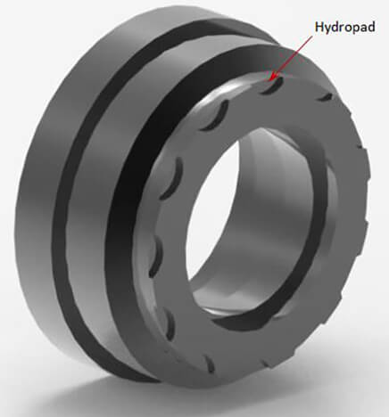 Image 5. Primary ring face with hydropads
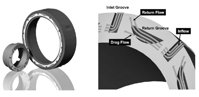 Image 6. Examples of special hydrodynamic structures.
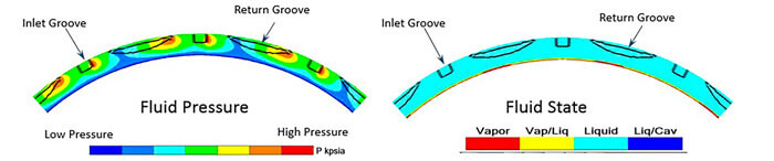 Image 7. Fluid pressure and fluid state.
FEA Simulation Tools
It is important to study the structural and thermal behavior of each seal component to estimate the longevity of the complete seal design. Individual parts or assemblies can be analyzed using CAE software, such as Abaqus and Ansys, which are based on FEA method. These tools offer solutions to engineering problems with linear or nonlinear behavior at steady or transient state conditions with complex interacting and contacting capabilities.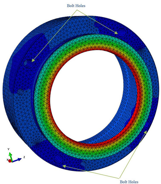 Image 8. Gland deformation at upset condition
Computational Fluid Dynamics
For successful seal application, it is equally important to understand the fluid flow phenomenon in the seal chamber. In the real world, it is close to impossible to actually see the fluid flow pattern in an enclosed system. Using a CFD program with its advanced technology allows users to reliably model the fluid dynamics. The CFD tool gives a great opportunity to design an optimum flow inducing device such as a pumping ring. Pumping rings come in various sizes and styles. Therefore, the CFD program comes in handy to estimate the flow and the pressure head generated by these devices before it is field installed. Based on the results, the engineer can make recommendations to ensure an adequate fluid flow at upset conditions, too. Maintaining fluid flow is critical for high temperature applications to help remove heat generated at the faces. Image 9 shows the CFD analysis of a pumping ring performance by estimating the pressure differential from the generated flow. The pumping ring performance curve is plotted with the developed head (by converting pressure to head) on the vertical axis for a given fluid flow rate on the horizontal axis. Because of the frictional losses in a piping system, which make up the system curve, the actual fluid circulation rate at operating point is determined by the intersection of the pumping ring performance curve and system curve.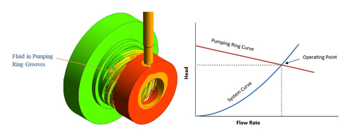 Image 9. Fluid pressure gradient from CFD analysis; pumping ring and system curve