
Part 1 of this series (Pumps & Systems, March 2015) discussed what happens to a boiler feedwater (BFW) pump during plant transients. The column included calculations that show what happens when the pegging steam supply to the deaerator (DA) is cut off: DA pressure drops, but condensate continues to flow, cooling the DA. We saw that the resultant two-phase fluid in the DA would contain a small vapor fraction when measured by mass, but the proportion of gas to volume is very large. The evolving vapor that is pulled into the downcomer pipe combined with the lowered suction pressure at the pump inlet can result in a pump trip. This trip is caused by insufficient net positive suction head (NPSH) and high vibrations. The essence of the process was shown in a video at pumpingmachinery.com/pump_school/pump_school.htm, PVA module #8. The cause of the problem in the previous column was a flashing of the DA. This column will examine what happens if the downcomer is connected to two pumps. In the example, both pumps are running before the plant transient event—such as a load rejection during a generator trip.
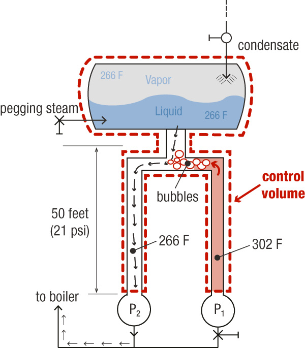 Figure 1. The system with two pumps (Graphics courtesy of the author)
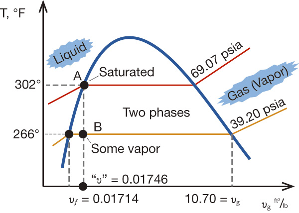 Figure 2. The T-v diagram shows the thermodynamics of the transient inside the DA and the piping.
Liquid to Vapor
The transformation from liquid to vapor is a complex process. It depends on many factors, such as pressure, the volume of the area into which the product can expand, insulation (adiabatic/isentropic process), conduction between adjacent media (such as a colder water in neighboring Pump 2). For our example, assume that the control volume—consisting of the DA plus both headers—is constant. This makes the transformation a thermodynamically constant volume process. As the liquid in the header of Pump 1 tries to expand into steam, it will first encounter cooler water at the junction to the piping to Pump 2. So the 302 F steam meets the 266 F liquid. According to thermodynamics, when a liquid that is transforming into vapor encounters a cooler liquid, the transformation happens in milliseconds. The heat vapor will cool it to liquid, but it will also heat up the cooler water in Pump 2. Eventually, the 302 F fluid would cool down to 266 F and come into thermal equilibrium with the water in Pump 2. A potential issue is whether the heating effect of the hot water on the cold water that flows to Pump 2 will be enough to raise its temperature above the saturation temperature and cause it to flash into steam. Even if the temperature does not increase that much, it could become hot enough for its vapor pressure reduction to reduce the net positive suction head available (NPSHA) at Pump 2 and cause cavitation or a pump trip. Consider an extreme scenario in which the two amounts of water, assumed to be equal in volume, mix instantaneously. In this case, the temperature would come to equilibrium at 284 F, the average of the two previous temperatures. The incoming DA water could provide additional cooling. Suction pressure at the pump inlet would be 60 psia. According to thermodynamic tables, the saturation pressure at 284 F is 52 psi a.1 This is 8 psi below the available 60 psia.Cavitation
For cavitation to occur, the pressure does not need to be exactly at vapor pressure. Some reduction of pressure will occur from the usual point of measurement to the area where the pressure actually does drop to vapor pressure, typically at the tips of the impeller blades. The 8 psi is roughly 20 feet of NPSHA and is usually sufficiently greater than the net positive suction head required of a typical BFW pump—especially considering the extreme scenario of the entire column of hot water in the pipe from Pump 1 instantly transmitting all of its heat to the water in the pipe in Pump 2. In reality, however, this transformation would be much more gradual. Plus, the water would be cooled by the continual resupply of the even colder water from the DA. The effect on the temperature of the colder water would be negligible. While vapor could possibly float to the DA and choke off the supply of water to Pump 2, the scenario is unlikely because vapor transforms to liquid almost instantaneously.Conclusion
In summary, the behavior of the DA has the greatest effect on a pump’s cavitation during power plant transients. The adjacent piping containing the trapped hotter fluids is unlikely to cause cavitation. The results will be different in every plant, and different piping and DA sizes, piping designs, pump speed, design, flow and insulation details affect how these systems respond to transients. References- Cameron Hydraulic Data Book, 19th Edition, 2002
- R. R. Cranfield, “Studies of Power Station Feed Pump Loss of Suction Pressure Incidents,” ASME, Journal of Fluids engineering, Vol. 110, December 1988
