Part One of this series (Pumps & Systems, November 2014) explained the general concept of slip in centrifugal impellers. This part will discuss how split vanes or alternating primary and secondary vanes can control slip in slurry pumps.
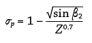
As early as 1927, Aural Stodola proposed to correlate the slip velocity to the number of vanes, Z, as well as the vane tip discharge angle, β2.
Equation 1:
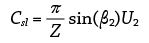 Z = number of vanes
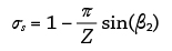
The Stodola slip factor at zero flow is expressed as
Equation 2:
Z = number of vanes
The Stodola slip factor at zero flow is expressed as
Equation 2:
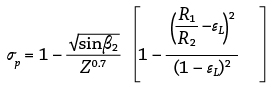
 F.J. Weisner developed an excellent review of slip factor equations, which showed that Equation 4 can be used up to a certain limit, εL, as expressed by Equation 3.8 Beyond that limit, Equation 5 must be used.
Equation 3:
F.J. Weisner developed an excellent review of slip factor equations, which showed that Equation 4 can be used up to a certain limit, εL, as expressed by Equation 3.8 Beyond that limit, Equation 5 must be used.
Equation 3:
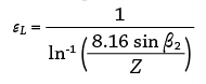 If R1/R2 <εL, then see Equation 4.
Equation 4:
If R1/R2 <εL, then see Equation 4.
Equation 4:
 If R1/R2 >εL, then see Equation 5.
Equation 5:
If R1/R2 >εL, then see Equation 5.
Equation 5:
Secondary or Split Vanes
A slurry impeller typically uses a limited number of vanes in order to prevent large particles and rocks from blocking the eye. A slurry pump impeller developed in 1994, however, consisted of smaller secondary vanes alternating with primary vanes (see Image 1).1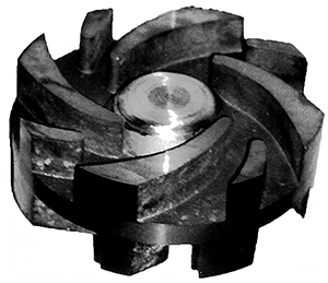 Image 1. The original impeller with alternating primary and secondary vanes, invented by Abulnaga1 (Images and graphics courtesy of Splitvane Engineers Inc.)
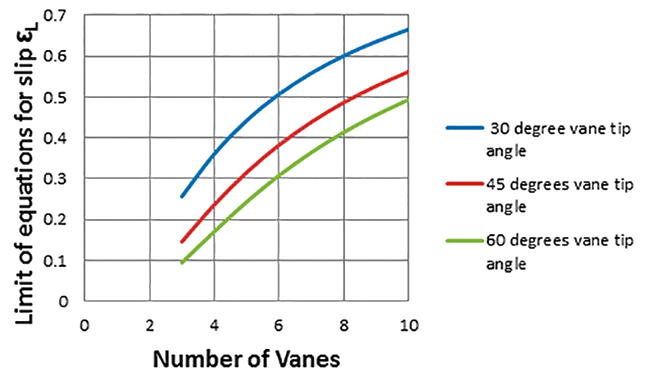 Figure 1. Limit between the slip (see Equations 4 and 5)
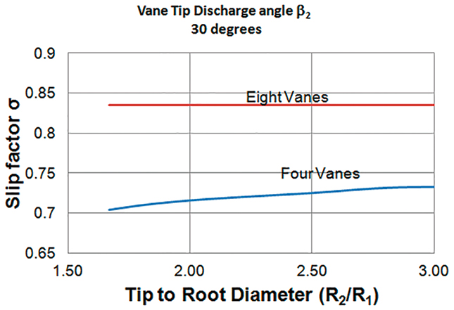 Figure 2. The beneficial effect that increasing the number of vanes has on slip factor with a vane tip angle of 30 degrees
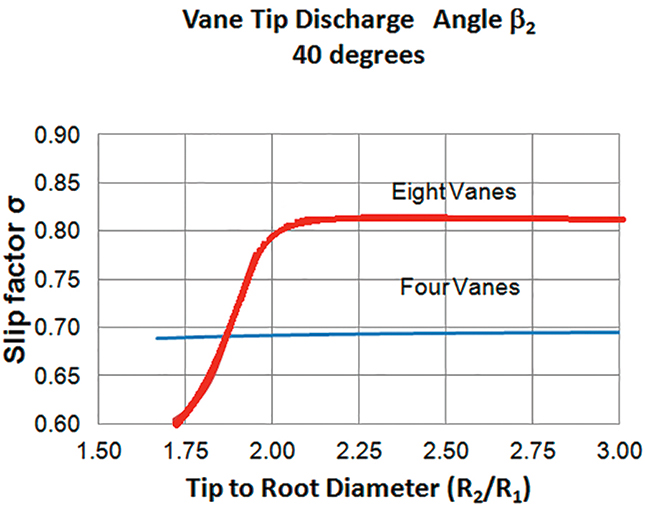 Figure 3. The beneficial effect that increasing the number of vanes has on slip factor with a vane tip angle of 40 degrees
Recirculation
As shown in Image 1, these secondary vanes are thinner than the primary vanes, but they affect the hydraulic efficiency by limiting recirculation, a problem that pumps experience when they operate away from their best efficiency point (BEP). Recirculation is a more significant problem with slurry pumps because the passageway becomes very wide toward the tip diameter. The American National Standards Institute (ANSI)/ Hydraulic Institute (HI) Standard 12.1 – 12.6 has certain recommendations for pumping through slurry pumps, away from the BEP.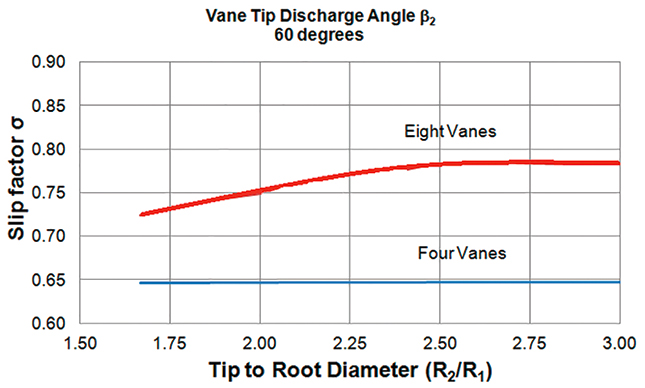 Figure 4. The beneficial effect that increasing the number of vanes has on slip factor with a vane tip angle of 60 degrees
 Figure 5. The secondary vane alters the pattern of recirculation away from the BEP.
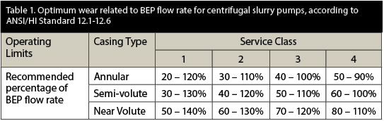
Conclusion
Slurry pumps provide a good balance of wide passage at the eye for rocks and the ability to resist wear. Secondary vanes or split vanes can help reduce head losses in the impeller, bringing the delivered head closer to the net theoretical head by reducing slip and altering recirculation patterns away from the BEP. They can also help break air bubbles that form when pumping froth and foamy mixtures. Further research in this area is recommended.References
- Abulnaga, B.E. (1994) – Patent Application CA2120977. Impeller with alternating primary and secondary vanes of different geometry. Filed November 11, 1994 – Filed in Canada.
- Abulnaga, B.E. (2002) – The Slurry Systems Handbook – McGraw-Hill 2002 – N.Y.
- Abulnaga, B.E. (2004) – Pumping Oil Sand Froth, March 2004. 21st International Pump Users Symposium, Baltimore, Maryland. Published by Texas A&M University, Texas.
- Cherakassky V.M. 1977 – Pumps, Fans, Compressors – Mir Publications – Moscow.
- ANSI/HI 12.1-12.6 - Rotodynamic (Centrifugal) Slurry Pumps – 1st Edition.
- Jekat W.K. 1992 – Centrifugal Pump Theory – Section 2.1 of Karassik I.J., Krutzch W.C. Fraser.
- W.H. and Messina J.P. The Pump Handbook, Second Edition. McGraw-Hill – 1985.
- Wessner F.J.1967. A Review of Slip Factors for Centrifugal Impellers – Transactions of ASME. pp. 558-572.
- Thin K.C., M.M. Khaing and K.M. Aye – 2008 – Design and Performance Analysis of Centrifugal Pump – World Academy of Science, Engineering and Technology – Vol 2:2008. pp. 10-22.