
The need for a leak-free pump became urgent in the modern age when industrial pumps began handling hazardous liquids. In the case of a toxic or flammable liquid, it is essential to protect both people and the environment from any leaks. Also, every leak means wasted product, which becomes significant when pumping expensive media, such as pharmaceutical materials.
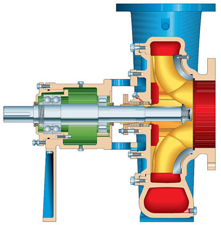 Image 1. Pump with a stuffing box (Images courtesy of ITT Goulds Pumps)
Why Do Pumps Leak?
Consider why it is so challenging to prevent pumps from leaking. Take the common centrifugal pump as an example. In this pump, a shaft and impeller are rotated by a motor, but the motor is located outside the pump. It is where the shaft exits the pump, specifically at the points of contact between the rotating and stationary parts, that leaks can and do occur.
The Stuffing Box
In some pumps, a device called a stuffing box is used to solve the leak problem.
The stuffing box is a chamber situated on the outside of the pump case where the shaft exits. Within it, sealing material—a soft packing substance—is laid around the shaft.
Using a special device (a nut in the simplest case), the packing is then compressed, causing it to press against the walls of the chamber and the shaft, thus preventing liquid from flowing out of the pump.
However, the shaft has to be in close contact with the packing material in order for the seal to be tight. This can create friction and lead to a shortened service life.
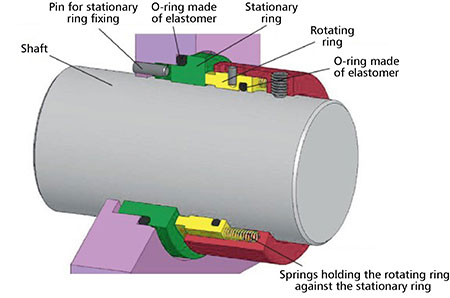 Image 2. Mechanical seal
Mechanical Seals
The main elements of mechanical seals are two rings: a moving one, which rotates with the shaft, and a stationary one, which is attached to the pump body with a pin.
Tightness against leaks is created by contact between the ring surfaces, which forms a so-called friction pair. To provide the contact, the moving ring is pressed against the fixed ring by a spring, spring unit or bellows—which is an elastic single-layer or multilayer corrugated sheath made of metallic, nonmetallic and composite materials. For additional sealing, secondary seals are used, which are O-rings made of elastomer.
The two rings are the only interacting surfaces in the sealing of the pump.
When working properly, a thin film of liquid is present between the friction surfaces to ensure lubrication and heat dissipation. The clearance between their surfaces is equal to their roughness height and, as a rule, does not exceed one millionth of a meter. Importantly, the fixed ring never touches the shaft, thus reducing wear.
Choosing the right seal ring materials is not a trivial task. The rings need to have sufficient strength and wear resistance to withstand the effects of pump operation and be chemically resistant to the pumped medium. In addition, they must be able to withstand the high temperatures that arise due to friction. For these reasons, friction pairs are surprisingly sophisticated technologies, requiring the theoretical and calculation disciplines of mechanics, thermodynamics, hydraulics and tribology. Due to the small clearance between the rings, the manufacture of modern mechanical seals actually falls into the category of nanotechnology.
Double Mechanical Seals
Single friction pair mechanical seals may only minimize leaks, not eliminate them. To further attempt to eliminate leaks, double mechanical butt seals were created. The auxiliary system—called a flushing plan or piping plan—feeds a special fluid, called a barrier, to the area of the seal between the two rings of the friction pair. Its pressure is held a bit higher than that of the pumped medium in the sealing area and, in this way, tightness is achieved. The barrier fluid also performs the necessary tasks of heat removal and lubrication in the event that the pumped media lacks the properties to do so. Water, for example, loses its lubricating properties at about 176 F (80 C).
Mechanical double butt seals can eliminate leaks of the pumped fluid to atmosphere. However, they can be relatively expensive and difficult to maintain. In addition, even the most carefully constructed friction pair will fail in time due to wear, so they require continuous monitoring and replacement.
Magnetic Couplings
The principle of magnetic coupling is based on the transmission of torque from the driver to the impeller of the pump using permanent magnets made of rare earth metals (Image 3). The motor rotates the shaft with the driving magnets attached to it, which are located outside a sealed pump casing. The driven magnets are located inside the pump casing and are attached to the impeller. The movement of the driving magnets causes the driven magnets to rotate.
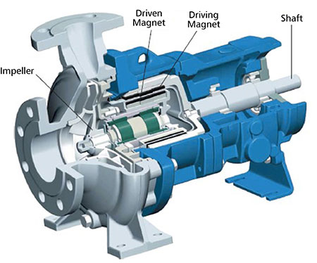 Image 3. Sectional drawing of a mag drive pump. The shaft with driving magnets rotates the cartridge, which includes the driven magnets.
Due to this remote transmission of power, the shaft does not need to pass through the casing, so there are no holes and there can be no leaks. However, these pumps tend to be more expensive, due to the cost of the state-of-the-art magnets they require. Usually, these are made of exotic alloys of neodymium, cobalt and samarium, but neodymium iron boron (NdFeB) alloy is now considered more effective. The service life of these magnets can be tens, or even hundreds, of years—often longer than the service life of the pump itself.
Canned Motor Pumps
The other advance that came about from the development of electromechanics and electromagnetic theory was the canned motor pump. This device combines the function of the electric motor with that of the classic centrifugal pump. It is similar to a pump with a magnetic coupling, but the role of the magnets is performed by the windings of the stator (fixed part of the electric motor) and the rotor. It is called “canned” because the motor is protected from short circuits by a special cylinder (shell) and located inside the pump casing in the pumped liquid, which simultaneously lubricates and cools the bearings.
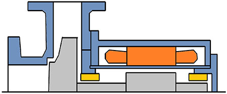 Image 4. Canned motor pump
The torque from the “dry” windings of the stator is transmitted through an airtight casing, so there is no possibility of leaks.
Because canned motor pumps use fewer parts, they are compact. However, because the coils of the stator and the rotor are separated by several partitions, their efficiency can be relatively low. Therefore, these devices are ruggedly useful but do consume more power.
Persistent effort over many years has now produced a variety of options to achieve a leak-free pump. Each has its own mix of advantages and drawbacks. To determine which is best for your operation, specialists will select a design depending on the properties of the pumped liquids, operating conditions and economic constraints.
