

Author’s note: This piece is adapted from the Pump Application Guideline for Water Treatment Plant Pumps.
The treatment of raw surface water includes the physical removal of solids and contaminants in the water, followed by disinfection to kill microorganisms and viruses. A conventional treatment plant contains many processes to support the removal of these contaminants resulting in treated potable or nonpotable water.
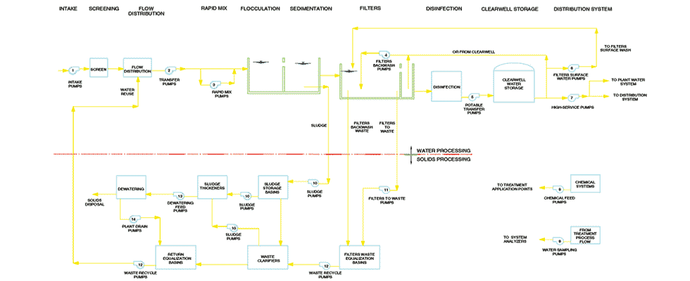
An excerpt from the Pump Application Guideline for Water Treatment Plant Pumps is provided in Image 1 and shows a conventional surface water treatment plant diagram that details 14 pumping processes, each of which requires a specific pump design to handle the various application requirements. For each of the pump applications listed in Image 1, there are typically several different pump designs suitable for the application. However, the designer cannot just pick from a recommended list. They must consider and evaluate all relevant application factors to ensure the pump system will operate efficiently and reliably.
The first criterion to consider is the source and quality of the raw water the intake pump station will supply to the plant. The raw water can come from sources such as groundwater, rivers, lakes, aqueducts and reservoirs. Water quality may vary considerably in solids content, physical, chemical and biological contaminants, temperature and ecosystem. The water quality is the first important consideration in the design of the pump station and selection of the pump and its materials; therefore, a water quality test should be done to help establish pump station design.
Focusing on Application 1, intake pumps, the intake pump station is designed to deliver raw water to the treatment plant with a capacity range to match the plant design. Due to variable treatment plant capacities, the number and size of the pumps selected will vary and must be capable of operating in parallel to deliver the variable flow. The selection of the number of pumps and the control of the pumps should maximize the pump operating time in the preferred operating region (POR), per American National Standards Institute/Hydraulic Institute (ANSI/HI) 9.6.3 Rotodynamic Pumps—Guideline for Operating Regions. Considering the quantity and control of the pumps to efficiently meet the treatment plant variable capacity will help reduce the total life cycle cost.
Pumps used in this application are designed to be suitable for pumping a wide range of flow and water quality, from screened, clear water to turbid water containing particulates such as sand, silt and other biological constituents.
Intake types that will be discussed in greater detail are:
- gravity intakes
- groundwater intakes
- river intakes
- lake intakes
Gravity intakes feed into the plant from an elevated reservoir or body of water above the influent structure. A control valve, gate or control weir regulates the flow into the plant. If the hydraulic condition exists to permit gravity flow throughout the capacity range of the plant, then an intake pump station may not be required.
Groundwater intakes use well pumps that supply raw water directly to the plant or to a storage reservoir that feeds the plant by gravity. Groundwater may include large amounts of sand. In that case, sand separators are used aboveground at the wellhead location. To reliably deal with sandy raw water, the pump materials are carefully considered so that components do not wear at an unacceptable rate.
River intakes divert from raw water to a pump station located as close as practical to the source. The river water quality may vary in physical, chemical and biological constituents. The intake design may need to pretreat the water upstream of the pump station by use of sedimentation basins to remove sand or silt, and typically a screen is required with spacing between 1.5 inches and 3 inches to remove large solids.
In some states, a fine screen may be required to protect fish from being drawn into the station. Lake intakes are similar to river intakes in that the pump station is located as close to the lake as possible. This will require similar water quality testing to determine material requirements and possibly require screening for large debris and fish.
For all intake pump stations, the inlet configuration must be designed so that the hydraulic flow conditions as raw water enters the suction volute of the pump will meet the criteria outlined in ANSI/HI 9.6.1 Rotodynamic Pumps Guideline for NPSH (Net Positive Suction Head) Margin, ANSI/HI Rotodynamic Pumps for Pump Piping, and ANSI/HI 9.8 Rotodynamic Pumps for Pump Intake Design.
Following these standards will help ensure adverse hydraulic conditions are not present, such as nonuniform flow, submerged vortices, free surface vortices, pre-swirl and fluctuation with time, nonuniform distribution of velocity and entrained air or gas at the impeller eye and significant pump cavitation.
Depending on the intake type, any of the following pump types are used:
- horizontal end suction rotodynamic (OH1)
- horizontal split case rotodynamic (BB1)
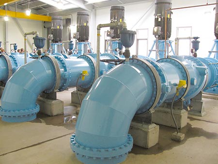
- vertically suspended pumps rotodynamic (VS1, VS2, VS3), Image 2
- submersible rotodynamic (VS0)
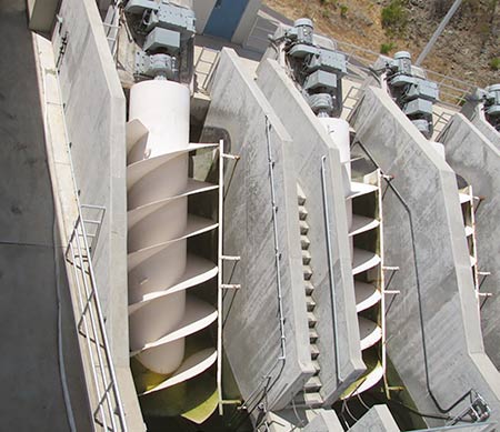
- Archimedes screw, Image 3
For more details on the construction and design of these pump types, reference ANSI/HI 14.1-14.2 Rotodynamic Pumps for Nomenclature and Definition, and ANSI/HI 14.3 Rotodynamic Pumps for Design and Application.
The following are vital to efficient and reliable operation: designing the pump station; selecting the right
pump design for the application; considering water makeup; materials of construction; piping and intake NPSH requirements; and control to operate in the POR.
The station designer must have a thorough understanding of the treatment process, its liquid composition, industry standards and best practices. The station designer must also work collaboratively with trusted pump manufacturers to ensure a successful outcome.
References
1. Water Treatment Plant Pumps: Guidelines for Selection, Application and Operation
2. ANSI/HI 9.6.1 Rotodynamic Pumps—Guideline for NPSH Margin
3. ANSI/HI 9.6.3 Rotodynamic Pumps—Guideline for Operating Regions
4. ANSI/HI 9.6.6 Rotodynamic Pumps for Pump Piping
5. ANSI/HI 9.8 Rotodynamic Pumps for Intake Design
6. ANSI/HI 14.1-14.2 Rotodynamic Pumps for Nomenclature and Definition
7. ANSI/HI 14.3 Rotodynamic Pumps for Design and Application
