

In olden times, when hard work beyond the ability of a few humans was needed, a horse or a team of oxen was the solution. Even greater power requirements were fulfilled by wind or water mills. This form of driving machinery lasted for centuries and the mechanical components involved required little in the way of alignment, beyond rudimentary good fits. When self-powered machinery was invented in the early 19th century in the form of James Watt’s steam engine, the pace of industrialization began to quicken. With this revolutionary power source, the volume of manufacturing increased rapidly and a greater demand for water and other fluids in industrial processes was created.
While early machinery often transmitted power via gear drives and flat leather belt drives, it did not take long for engineers to realize that directly coupling the driver to the driven machine would result in improved efficiency of power transmission with all the savings entailed therein. It is only with the invention of modern multiple V-belt drives with negligible stretching and slippage that the efficiency of belt-driven systems again rose to compete effectively with direct-drive systems.
In early days, speeds of rotation were slow and alignment of both belt-driven and directly coupled machines was traditionally accomplished by eyeing it, using a straightedge and feeler gauges. Good machining of surfaces and great care were usually all that was needed to obtain a satisfactory result. This modus operandi persisted through the 1940s. By the end of World War II, the United States was in a commercial position that favored industrial production: almost all of the world wanted manufactured goods, and the U.S. was a principal source for them. If someone wanted a car, a TV, or a sheet of stainless steel, it was likely made in the U.S. Global competition did not exist to nearly the extent that it does today, so cost-consciousness was not what it is today. Resources were plentiful, environmental regulation minimal and craftsmanship excellent. Plants could afford to install standby machines for all critical processes and concrete foundations were poured a little deeper. People designed machines using slide rules. Today, computers trained to shave away every unnecessary ounce of metal do the designing.
In the 1930s, the average speed of rotation of an electric motor was 900 or 1,200 rotations per minute (rpm). Back then, the straightedge was king. Pumps had stuffing boxes, and when they sprang a leak, the mechanic simply tightened the packing glands to compress the braided cotton and asbestos packing rope until the leak went away. Often, the shaft was later found to be scored from the pressure of overtightening. As industrial production flourished and a wide range of new products were introduced, harsh chemicals demanded different containment approaches and mechanical seals became more prevalent. This demanded precision alignment. As technology improved, and Europe came online again with significant industrial production, the 1950s saw speeds of rotation increase to an average of 1,800 rpm. It was quickly discovered that as speeds of rotation increased, the need for good alignment also increased—not just in linear proportion, but exponentially.
The straightedge could do a fine job with offset misalignment if used with care on coupling surfaces of well-bored couplings; but who could consistently guarantee such conditions? Yet, it was not good enough with regard to the angularity between the shafts. This was due to the limited measurement resolution afforded by eyesight over the short span of the straightedge across the coupling hubs. As apprenticeships and general craftsmanship declined, the assurance that a coupling was machined concentric to the mechanical centerline of rotation, and that its faces were perpendicular to said centerline, or even that it was entirely round, waned. Also, foundations became weaker and not as flat as they ought to have been. Put simply, the alignment of surfaces via a straightedge or a dial indicator rotated around a shaft (not with the shaft) were no longer good enough. New ways to align the actual rotating centerlines of machines needed to be devised, and now the dial indicator (formerly strictly a machinist’s tool) came into its own. Its use by millwrights in machinery shaft alignment did not really take off until after WWII. Now the so-called “rim and face” method became king.
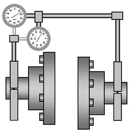
A radially mounted (rim) indicator, and an axially oriented (face) indicator were firmly affixed to one shaft—or to its solid coupling hub—and were made to indicate one particular location on the opposite shaft or hub as these were rotated in unison. This was a step in the right direction. Gone was the need to uncouple the flexible coupling and the reliance on concentricity and surface perfection. True shaft alignment of the centerlines of rotation was born. The rim indicator measured the offset or separation between centerlines, and the face indicator measured the gap difference that occurred from top to bottom and from one side to the opposite, thereby allowing the angle between the centerlines to be established by dividing the observed gap difference by the diameter of the face indicator’s travel. Simple rise over run.
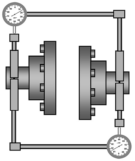
Of course, end float (axial play) and hardware sag due to the cantilevered bracket setup still impacted the accuracy of the readings. This meant careful work and good training were still needed to achieve satisfactory results. To overcome these problems, a new approach to using dial indicators was devised in a petrochemical refinery in Houston, Texas, in the 1950s. This new approach was deemed so valuable that its “secret” was closely held for a long time. It was called the “reverse indicator” method, wherein the face indicator is entirely dispensed with and only two radially mounted indicators are used, one each bridging across the coupling in opposite directions and indicating the opposing shaft or hub at opposite ends.
This eliminated most of the effects of end float and reduced the sag by only having to hang one indicator instead of two at the end of the bar that bridged across the coupling. This made the job easier, more accurate and faster. Offset was still measured directly, but the angle was now extrapolated by looking at the difference in offset readings across the span between the indicators rather than by looking at gap differences. The main advantage of this approach is it was more direct, less error-prone and more highly resolved, since for any given setup the span between rim indicators will likely be greater than the diameter of face indicator travel on the same setup. The reverse indicator method still had drawbacks, however, such as being harder to understand and, thus, requiring more training. Also, it did not eliminate the need for manually calculating alignment conditions at the plane of power transmission and corrections at the machine foot locations. The use of the reverse indicator method did not filter out of the petroleum industry to the rest of industry until the 1970s, and even today, if indicators are used, the reverse indicator method is seldom used in comparison to the rim and face approach, except in the petrochemical industry.
In the 1980s, global competition, greater cost-consciousness and computerized technology became the status quo. This meant that fewer standby machines and less rugged, more delicate machines were made to do more with less mass at higher speeds. Production downtime became a manager’s worst nightmare. Now, faster electric motors were the norm, and vibration analysis and condition monitoring technology improved. More energy-efficient, high-speed gas and steam turbine-driven machines were installed. The trusty dial indicator was not delivering the performance needed in a reasonable amount of time, especially considering that finding and correcting machine frame distortion (soft foot) was a vital part of the alignment job. This was also a task performed with dial indicators, and as the criticality of machines increased at the same time their physical structures became more less rugged, the reliability of indicator readings taken at the feet decreased.
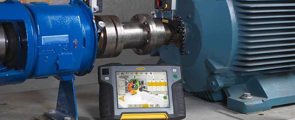
Then, along came laser. Laser-based shaft alignment technology with preprogrammed alignment condition and correction calculation debuted in 1984. Laser alignment was ahead of its time then, so the concept of alignment and its importance was not understood or was underrated by maintenance departments. Today, laser shaft alignment is ubiquitous and allows any mechanic, trained or not, to perform even complicated shaft alignments. Modern systems allow accurate alignment readings to be taken with less than a quarter turn of the shafts and corrective moves of the machine to be monitored live without the need for placing dial indicators against the feet. Soft foot can now be directly measured in terms of its impact on shaft movement rather than foot movement (vital in establishing the severity of machine frame strain) and long spacer coupling spans can be measured with relative ease, without the need for constructing “Christmas tree” indicator bracketing. Cooling tower fans, a particular challenge to maintenance departments and mechanics working with indicators, have become easier to deal with.
Deliberate misalignment of critical boiler feed pumps to compensate for thermal growth was likewise a feared task, when neither plant engineering nor maintenance had adequate training to understand these issues properly. Modern laser systems permit the millwright to enter thermal growth targets for offsetting and angling the machines when cold, so they can grow into alignment as they warm up and are put under load. In the past, various systems for monitoring positional change in running machinery had been devised. Today, a laser system permits the direct monitoring of relative or absolute positional change in running machinery from a cold, stopped, no load condition to the fully hot, loaded, running condition—all without being affected by heat or vibration. True targets can now be developed that take into account thermal growth, dynamic load shifts, pipe strain and other movement-causing factors.
High-speed multiaxis detectors with built-in automatic inclinometers freed the millwright from the need to rotate shafts together to specific clock positions, and uncoupled alignment could now produce accurate results with a so-called uncoupled sweep mode obtained with less than a quarter turn of the shafts, starting and stopping anywhere. This was a revolutionary development—shaft alignment became easy for mechanics who could now do this job to a high degree of accuracy.
Results are evaluated with regard to permissible tolerances (either to American National Standards Institute [ANSI] standards or to the user’s own in-house criteria) and are displayed as graphical centerlines to scale. This means the results can be understood by an operator with no prior training. Further, shafts that were hard to turn and stop or jerky, such as hammer mills, could be accurately aligned as well via a multipoint measurement mode. Aligning vertical flange-mounted pumps and motors were no longer a problem either, given the ability to calculate shimming corrections for circular flange and anchor bolt patterns.
In today’s data-driven world, a reporting capability and file storage is standard with the modern laser systems. Thus the user does not have to document the work and results manually, but can generate a professional report directly from the instrument, thereby reducing risk of error and fulfilling various requirements of the International Organization of Standardization (ISO)-9000.
The benefits of precision laser shaft alignment have become widely recognized. Maintenance departments rely on laser alignment for reducing downtime, increasing efficiency and diminishing repair expenses, impacting parts as well as labor budgets. Poorly aligned machinery has largely been eliminated where a good laser system was employed, and laser alignment training is a key component of a user’s continuing education.
Read more Maintenance Minders articles here.
