

Within many industrial processes, gas is moved at pressures less than atmospheric. With different vacuum levels, the design of components includes consideration for the volumes at a pressure less than atmospheric or vacuum level.
Components of a Vacuum Pumping System
Image 1 shows a vacuum pumping system consisting of typical components (A through J) for moving gas in an industrial process. A vacuum gauge (G-1) and (G-2) displays vacuum level at the inlet of the vacuum pump. The operating vacuum is a pressure less than atmospheric or barometric pressure (A). A positive displacement vacuum pump (H) has an important reverse flow seal. A discharge pipe (J) is open to the atmospheric or barometric pressure to discharge the gas from the system.
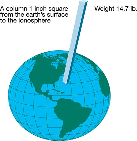
Image 2 shows a graphic description of standard atmospheric pressure measured at sea level. A 1-inch square column of air from sea level to the ionosphere, where there is no air, weighs 14.7 pounds at sea level. Using this form of measurement is impractical. In comparison, a 1-inch square column of mercury (Hg) that weighs 14.7 pounds is 29.92 inches, or 760 millimeters (mm) tall. Mercury is used in a U-tube barometer as a gauge.
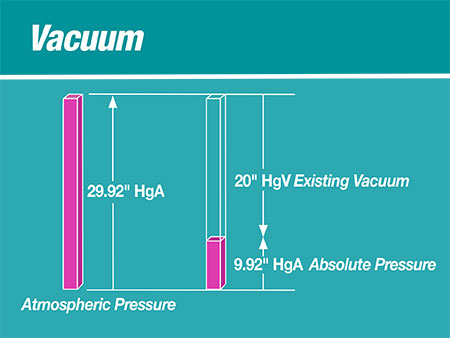
If absolute pressure (HgA) is visioned as a positive upward vector, then vacuum pressure (HgV) is envisioned as a downward vector. A calculated pressure absolute (as an upward vector) for a pressure vacuum (as a downward vector) is an upward pressure absolute less than atmospheric pressure absolute.
A vacuum pump is a positive displacement mover of a constant volume of gas. According to Boyle’s Law, P1V1 = P2V2 where P is always expressed as pressures absolute, HgAbsolute, HgAbs or HgA. Volumes (V) are cubic feet or cubic meters at a respective pressure (P). For vacuum systems, less than atmospheric pressure is expressed as inches of mercury HgV. In the chemical industry, closed vacuum systems with low vacuum need to be described as a very low pressure absolute HgA.
Vacuum gas is a part of many industrial processes at pressures less than standard pressure, or the local atmospheric or barometric pressure. Vacuum pumping is needed for vacuum filtration to yield liquid filtrates or solids: dewatering paper slurry, packaging of perishable food, pneumatic conveying of solids, extracting noncondensable gases from steam condensers and more. The two basic systems are a closed system (Image 3) and an open to the atmosphere air system (Image 1).
Closed System
The vacuum (lower than atmospheric pressure) gas, with possible entrained liquid, enters a vacuum pump by molecular velocity energy explained as the kinetic molecular energy theory. From the Kinetic Molecular Theory (KMT) of energy, all gas molecules have high velocities traveling in random directions. The flying molecules eventually hit the walls of a container, thereby developing pressure on the inside wall of the container.
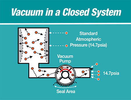
Image 4 shows the components of a closed system where a container of gas is reduced in pressure (vacuum) by the KMT. The vacuum pump is a positive displacement mover of a constant volume of gas. As more molecules at high speed exit the container and enter the pump, the resulting container pressure is decreased or the vacuum level increases. There is a key part of the vacuum pump called the seal area that makes this possible. There is atmospheric pressure at the outside of the vacuum pump discharge port capable of entering the back of the pump. The seal area prevents this outside atmospheric air from entering through the discharge port and passing into the inlet side of the pump. This would rob space from the inlet gas wanting to enter the pump, thereby decreasing the vacuum pumping of gas.
Examples of industry closed-vacuum systems include food vacuum packaging, batch-drying of pharmaceutical drugs and synthetic oil to achieve zero entrained water in the oil that fills high-voltage transformers, municipal anaerobic waste treatment digester pump of combustible gases and autoclave sterilization of medical instruments to vaporize liquid at lower pressures or vacuum.
Open System
An open system adds a process pipe for gas and other materials to enter the container like the closed system. Vacuum pumps cannot pull process gas into the vacuum box or container. There must be a driving pressure—typically atmospheric pressure pushes gas and other materials toward the vacuum pump. Standard atmospheric pressure (A) by its weight pushes into and through a medium (B), typically a filter screen or moisture-absorbing fabric. There will be a velocity and pressure drop across the screen or fabric, producing a gas pressure vacuum (C) less than pressure atmospheric. Between the medium and the vacuum pump inlet, the system works as a closed system, using the KMT to move the gas out of the vacuum container and toward the pump.
The process flow through a screen or fabric may contain particles of liquid or foreign material. If those materials could damage the pump, an inlet vacuum separator (D-1) will remove them. A vacuum pump is a gas pump, not a liquid pump. Since the inlet vacuum separator of an open system is under vacuum, an unloader pump (D2) or barometric drop leg (D-3) is used to extract the unwanted liquid or materials under vacuum.
If the vacuum pumping system uses a liquid ring for operation, a discharge silencer separator (J) is needed to separate the discharge ring liquid and the higher-than-atmospheric gas being discharged from the vacuum pump. The separated ring liquid can be discharged from the discharge silencer separator with gravity drain to the atmosphere.
Examples of Open Systems
- Paper machine dewatering in the formation section where <10% pulp, balance water is drained by gravity and low vacuum to increase the pulp concentration to about 20%.
- Paper machine dewatering in the press section where porous fabrics are used to absorb water from the paper sheet. The saturated fabrics are vacuum dewatered at vacuum suction boxes in an open system. Inlet vacuum separation of process water and gas protects the pump from material building inside. The fabrics are conditioned by saturating them with shower water and cleaned by suction boxes in an open system to remove fibers and extend its usefulness.
- Mining, such as phosphoric acid producers, uses an open vacuum pumping system on filters to extract liquid phosphoric acid and leave gypsum cake.
- Corn starch producers use an open system on filters to extract water and/or alcohol and retain dried corn starch.
- Chicken and fish meat producers use vacuum guns to remove body parts and pneumatic conveying of materials to collecting tanks. Inlet line material separators (D-1) are essential to protect the pumps from unwanted materials.
- Municipal aerobic waste treatment plants use vacuum filters to dry biological sludge to form waste cake and discharge water.
- Removing noncondensable gases from a steam condenser of a steam turbine.
Operational Adjustments
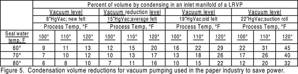
- Inlet gas condensing of moist hot process air can reduce vacuum pumping volume by injecting cooler spray water in Image 1 (F). When the temperature difference between inlet gas and condensing spray water is large enough to condense a part of the hotter water vapor in the inlet gas, volume reduction condensing can be added to the vacuum inlet piping in Image 1 (F). Image 5 gives temperature difference combinations coming from paper industry applications that will produce meaningful volume reductions to the vacuum pump, thereby reducing power requirements for pumping.
- Adjust seal water flow at Image 1 (H) to a liquid ring pump for maximum stable vacuum. Seal water flow has four functions in a liquid ring vacuum pump:
a) Form pistons between rotor vanes to compress the inlet gas.
b) Remove the heat of compression, typically 15 F temperature rise per revolution, to avoid cavitation (vaporization) of the seal water.
c) Make a positive seal to prevent high pressure discharge gas from “slipping” into the inlet segment and rob space for new inlet gas to enter the pump, thereby reducing the gas moved.
d) Lubricate the shaft packing rings or mechanical seals.
