

The O.N. Stevens pump station in Corpus Christi, Texas, was originally designed in the mid-1950s. The pump station is configured with the two pump buildings connected to two common discharge lines.
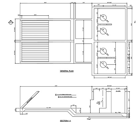 IMAGE 1: Plan and section of O.N. Stevens Nueces River intake (Images courtesy of LAN)
The original pumping station, located in pump building 1, was planned with several design deficiencies, especially the pump intake design (Image 1).
First, the placements of the pump intakes were more than 13 feet away from the back wall. Second, the pump bays flared out from the approach channel after the screens. Third, the bays for the two pumps on the north were not symmetrical about their intake channel. This situation was mirrored on the south. As a result, the vertical turbine pumps in the pump station suffered from operating issues and impaired service life.
As part of a team working on providing additional water supply capacity for Corpus Christi, a national engineering firm was contracted to evaluate the existing pipeline hydraulic capacity of transfer lines from the O.N. Stevens pump station to the treatment plant. In addition, the firm was chosen to select pumps that would provide the desired capacity when both pump building 1 and pump building 2 were operating.
When the team originally visited the existing building No. 1, only one pump was installed. The project team was informed that the pumps in this building had always had problems. Through cursory observations, it was immediately obvious that the intake design of pump building 1 did not meet today’s design standards and contributed to the pump failures that had plagued this installation.
Hydraulic Institute Standards
The Hydraulic Institute (HI) Standard Rotodynamic Pumps for Pump Intake Design has 12 criteria for when a physical modeling study of pump intakes should be conducted. The O.N. Stevens pump station met six of these:
The intake design is not a standard design. Features such as bay width, bell clearances, sidewall angles, bottom slopes, distance from obstructions, the bell diameter, submergence, or piping changes, etc., deviate from this standard.
There is no prior physical model study for the intake design.
Nonuniform or nonsymmetric approach flow to the pump sump exists (intake from a cross flow; use of dual flow or drum screens; use of elbows, bends or multiple screens just upstream of a trench-type wet well; or a short-radius pipe bend near the pump suction).
Proper pump operation of a critical service or application as defined by the customer (such as a safety-related system).
Pump repair, remediation of a poor design, and the impacts of inadequate performance or pump failure would cost more than 10 times the cost of a physical model study.
The pumps have flows greater than 40,000 gallons per minute (gpm) per pump, or the total station flow with all pumps running would be greater than 100,000 gpm.
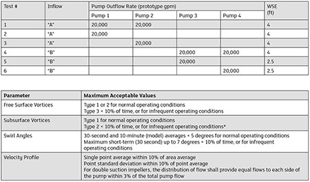 IMAGE 3: Note: Inflow “A” was used to simulate river flow to the northern pump train (pumps 1 and 2), and inflow “B” was used to simulate river flow to the southern pump train (pumps 3 and 4).
When designing an intake, the probability of failure should be considered by comparing the proposed design to other proven intakes that operate successfully. Specifically, the existing pump building 1 intake structure did not meet HI standards for pump intake design (HI 9.8). The variances from HI 9.8 included:
- The straight-run approach from the screens to the pump is too short.
- The pump well has an abrupt increase in width compared to the approach from the screens.
- The pumps are located too far from the back wall.
- The pumps are not centered between the wing walls.
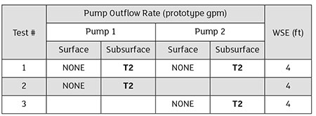 IMAGE 4: Free and subsurface vortices
BOLD indicates condition does not meet HI criteria
Free surface vortex acceptance criteria: type 1 or 2 for normal operating conditions and
type 3 < 10 percent of time, or for infrequent operating conditions
Subsurface vortex acceptance criteria: type 1 for normal operating conditions and
type 2 < 10 percent of time, or for infrequent operating conditions
These variations from HI 9.8 can lead to conditions that can negatively impact pump performance. These conditions include:
- Unacceptable vortex formation, which can lead to localized pressure reductions at the pump impeller, air entrainment and possibly cavitation.
- An increased possibility that the fluid entering the pumps will swirl, introducing a rotational component to the flow at the pump impeller and possibly vortex-like pressure reductions.
- A nonuniform flow distribution approaching the pumps, which results in different flow into four quadrants of the pump inlet.
- Unsteady flow, which results in flow changing with time into the four quadrants of the pump inlet.
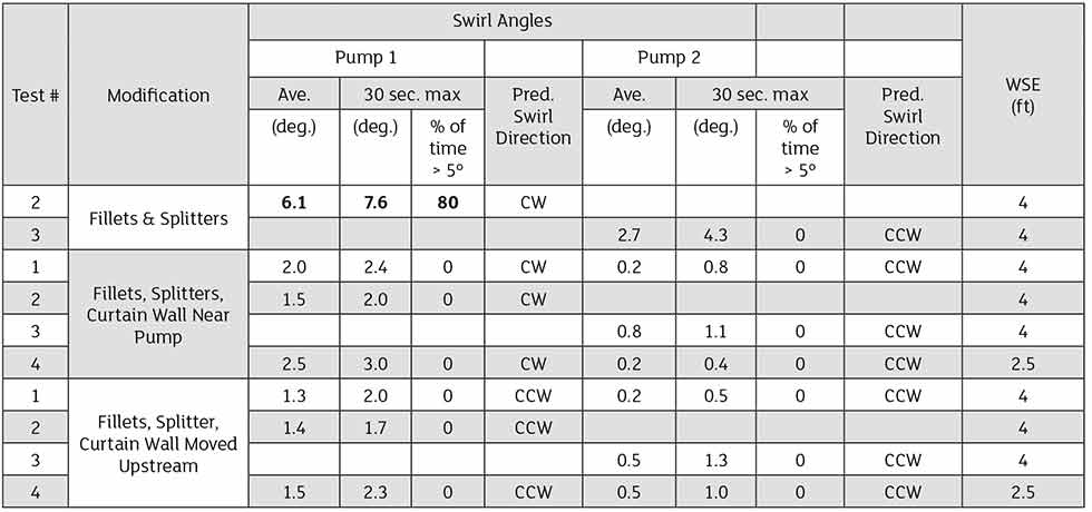
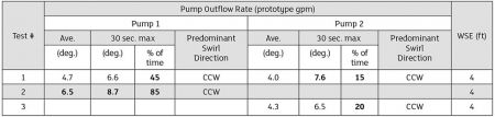 IMAGE 5: Swirl angle
BOLD indicates condition does not meet HI criteria
HI swirl angle acceptance criteria: average < 5 degrees and maximum short-term (30-second model) up to 7 degrees < 10 percent of the time
CW = clockwise swirl, CCW = counterclockwise swirl, viewed from above and looking downstream
These conditions can impart stresses on the pump bearings and cause premature wear. In extreme cases, it can lead to early pump failure. The existing nonstandard geometry would likely cause nonuniform split between the pumps and currents and impact the pumps, as indicated by the station history. Some corrections to the existing pump intake design could be corrected by relocating the pumps and changing geometry to more closely conform to standard intake design.
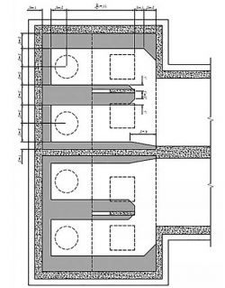
However, the intake design would still not meet standard qualifications. See Image 2 for the proposed modifications. HI 9.8 recommends modeling when design recommendations are not followed.
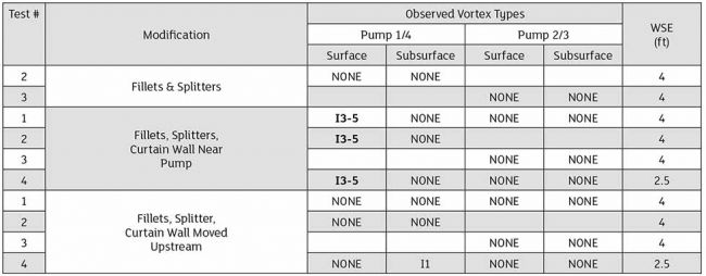 IMAGE 6: Modification testing — vortex identification
“I” indicates vortex is intermittent
BOLD indicates condition does not meet HI criteria
Free surface vortex acceptance criteria: type 1 or 2 for normal operating conditions and type 3 < 10 percent of time or for infrequent operating conditions
Subsurface vortex acceptance criteria: type 1 for normal operating conditions and type 2 < 10 percent of time or for infrequent operating conditions
Test conditions 1 to 3 are for pumps 1 and 2 only; test condition 4 is for pumps 3 and 4 only
Physical Model
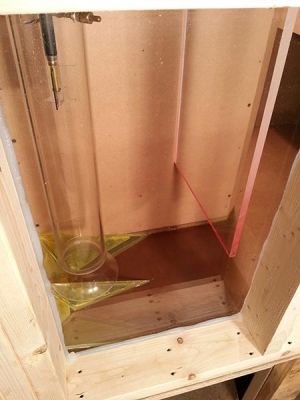
A physical model was initiated to determine if pump intake parameters could be met with the envisioned modifications that would allow proper intake conditions. The physical model was subsequently launched in partnership with a hydraulic modeling research laboratory.
Baseline Testing
In Phase 1, the pump station design was evaluated for six operating combinations. Image 3 shows the baseline test matrix consisting of pump combinations with one or two pumps operating (future flows) and corresponding water elevations.
The hydraulic performance was evaluated based on the HI acceptance criteria. If three test conditions clearly showed unacceptable flow patterns, flow distribution, vortices and/or swirl, Phase 2 would be initiated to derive modifications.
Acceptance Criteria
The following acceptance criteria—based on HI—were used to evaluate the hydraulic performance (as indicated by the model study results) to select a final modified design.
Velocity profile
The station is symmetrical about the centerline, and the wet well and bays are offset from the approach channel. This geometry, coupled with the river flow direction, results in a skewed velocity profile approaching the bays and pumps.
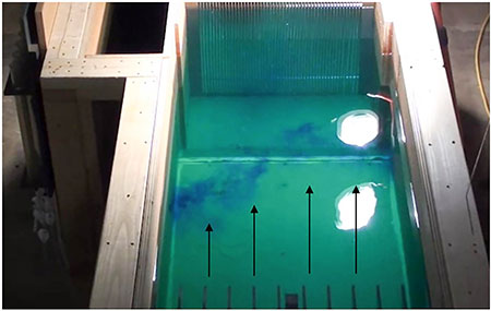
For test conditions 1 through 3, the flow in the approach channel was slightly skewed toward the center of the pump station. This uneven approach flow to the pump bays was most dramatic for test condition 2.
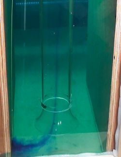
Free & subsurface vortices
The subsurface vortices, observed with dye at pump 2 during test condition 3, are shown in Image 4 and are representative of all baseline test conditions. The baseline vortex observations are shown in Image 4.
Swirl angle
At any given pump and test condition, the swirl was predominantly in one direction. All baseline swirl data is shown in Image 5. The model results proved that the initial geometry modifications were insufficient to provide ideal intake conditions.
Additional remedial structures were proposed by the modeling consultant, which were subsequently modeled.
Modification No. 1: Fillets & Splitters
Side and back wall fillets and a center floor splitter were investigated to eliminate the subsurface vortices and decrease
pump swirl. Modification No. 1 did eliminate subsurface vortex formation at both pumps.
This reduction in vortex formation resulted in a decrease in the swirl angle at pump 2, bringing the pump 2 swirl angle within HI criteria with an average 30-second maximum swirl angle of 2.7 and 4.3 degrees, respectively.
However, a modest reduction in pump 1 swirl angle with modification No. 1 demonstrated that subsurface vortices were not the main contributor to swirl at pump 1. Thus, the skewed flow distribution to pump 1 predominantly generated swirling flow in the bay.
Modification No. 2: Fillets, Splitters & Curtain Wall
A curtain wall was installed in conjunction with the fillets and splitter in an effort to further reduce the swirl at pumps 1 and 2.
At first, the curtain wall was installed 1.6 times diameter (D) of the inlet pipe from the pump centerline, and 1.2 D off the floor, as shown in Image 5.
However, a surface vortex set up just upstream of the curtain wall in bay No. 1 meant air bubbles were occasionally
pulled into the pump.
To eliminate this, the curtain walls were incrementally shifted upstream. The final location was 114 prototype inches upstream of the back wall of the bays.
At this location, no unacceptable vortices were observed.
These remedial structure modifications improved the inlet flow to bring the intake parameters into acceptable limits. The design went on to incorporate these modifications.
BOLD indicates condition does not meet HI criteria
HI swirl angle acceptance criteria: average < 5 degrees and maximum short-term (30-second model) up to 7 degrees < 10 percent of the time
CW = clockwise swirl, CCW = counterclockwise swirl, viewed from above and looking downstream
Test conditions 1 to 3 are for pumps 1 and 2 only; test condition 4 is for pumps 3 and 4 only
