

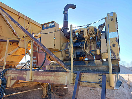
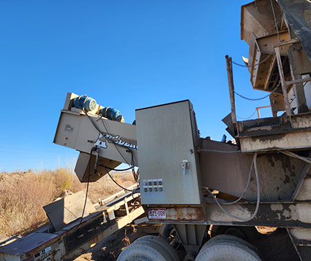
An aggregate processing plant had experienced a prolonged outage of one of their main screen sorting machines due to failure of the main regulator on the power generator. This 100-kilowatt diesel generator provided electrical output, both voltage and current, to a large 40 horsepower (hp) electric motor that powered a large vibrating screen to sort gravel according to size. The generator also powered a variable frequency drive (VFD) that controlled two other electric motors that ran the auger to remove the unwanted larger gravel particles. This heavy-duty equipment had been in operation since the early 1970s, so wear and tear and age came into account for the failure of the regulator.
Once the regulator was diagnosed as the main issue of the outage, a replacement was sourced. Since this generator had been operating since the early 1970s, and with the issues with supply chain deliverables in the last year, an exact replacement was not available. The generator’s original equipment had a three-phase rotating field where the replacement only required a two-phase rotating field. Unfortunately, this caused another issue. When starting an electric motor across the line, it requires six to 10 times full-load amps (in-rush current). The new regulator was not set up to control the delay that it takes to handle this amount of in-rush current for the time required for the motor to come up to speed. The regulator reacted to this with an overload situation and immediately blew the 100-amp fuse.
From here, the troubleshooting started to focus on the large 40 hp motor. An electric motor testing company was brought in to perform offline testing on the motor from the motor cabinet. Upon opening the cabinet, the test engineer found a large nest of yellowjackets that had to be dealt with prior to any troubleshooting. Once
that was handled, all normal offline tests were performed.
These consisted of resistance, inductance, impedance, capacitance, insulation resistance, step voltage and surge. The motor passed all tests within parameters. Other troubleshooting consisted of checking all the cables for continuity, checking the stator ground and also checking the generator rotor’s rotating field. These also checked good.
Next, the motor was started in a no-load situation. The shroud was removed along with the belt, and the motor and system performed correctly. This verified that the motor was in good working order. From here, the engineer started to look at the generator and regulator and asked questions about the third wire from the previous regulator not being used. From previous testing experience and general wiring of equipment, the engineer asked
if the original regulator was still available and was informed that it was over in a
scrap pile.
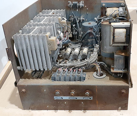
The discussion that followed determined that the best way to move forward might simply be to overhaul the old regulator and see if it could be repaired with new replacement components and other sourced old components. Since the aggregate company was reaching the limit of stone stock and needed a solution to get restarted, this was the best approach to alleviating the downtime issues.
Troubleshooting a 50-Year-Old Regulator
There were several issues that needed to be addressed when the troubleshooting started; first and foremost, understanding what this regulators job was in this machine system. The regulator was designed to robustly handle the transient voltage that is present at startup allowing time for the motor to spool up to operating speed and basically handle the push and tug between the generator and motor so that they did not damage each other.
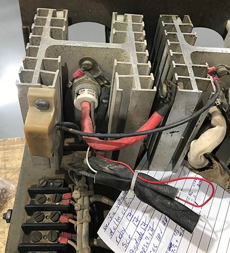
The problems that were found after initial inspection of each accessible component included shorted direct current (DC) supply rectifiers, shorted regulating silicon-controlled rectifiers (SCRs), a blown Phase 2 fuse with two others beyond end of life. Also, the three control wiper arms for droop, voltage and gain adjustments were either completely open or intermittently open and had heavy oxidation on the surface of the parts. The most surprising find was an uncrimped connection on one of the SCRs that made the engineer question how the machine ever worked properly, let alone for 50 years.
There were many other loose hardware and electrical connections; however, they all probably lost tightening from vibration. The one noncrimped connection could have begun the cascade of other failures that occurred. Of course, the age of the regulator also contributed to the failure of the unit.
After the initial inspection and diagnosis of the problems, the race was on to find old new stock of some of the parts or new equivalents that could be fit into the regulator to get it back into working order. Once parts were researched and ordered, then the real work began. The oxidation on the control wiper arms was cleaned making the droop, voltage and gain adjustments viable again.
It was determined that the droop and the gain were set in reverse, with droop being at minimum and gain at maximum. They needed to be set the other way with droop at maximum and gain at minimum. Having these settings correct is extremely important. These settings control the startup of the motor and allow the entire system to come up to speed and endure the in-rush current. The third arm setting for voltage would have to be set upon reinstallation. It was returned to as found prior to the repair attempt.
Unfortunately, some of the exact rectifiers that were acquired from a source that carried new old stock were not viable, creating more obstacles. New stock rectifiers were installed. After clean-up was completed, the way for this unit to be tested was to install it back into the machine and hope for the best.
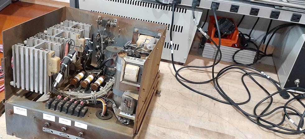
Refitting the Regulator
After the repairs were complete, the reinstallation process could begin. Some wires still had labels, while others did not. A representative of the OEM was contacted to try to see if a schematic of the wiring connections existed. Through a bit of a hunt, one was located and wiring began. After a bit of investigation and measurements of wire length to connection was completed, a trial-and-error startup was established.
The regulator was putting out 513 volts, which put the VFD in an overvolt state. It immediately shut down to protect itself and the motors that it drives. While waiting for the VFD to come back online, the voltage screw sweep arm was adjusted to bring the voltage into line with operating parameters. It was returned to its as found or original position during repair. This was at full power, which, with new parts, was not needed. The regulator was turned down until it measured approximately 486 volts.
Once again, the system was started, this time with a different outcome. The unit came online and operated according to specifications. A few weeks after the installation, an operation checkback was completed. The piles of aggregate were found larger, and the machine system was in full operation upon arrival.
