

A variable frequency drive (VFD) powering an electrical induction motor may sometimes trip off or signal an alarm to an operator. In some cases, this is due to errant operation, utility disturbance, product shortcoming or communication error. In other situations, it could be an indication that the load is in excess of the VFD’s present parameter settings or the motor’s ratings.
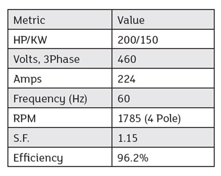 IMAGE 1: Induction motor ratings, TEFC, 841 Type (Images courtesy of Eaton)
This article will describe an on-site interaction with a plant end user operating a slurry pump and how the VFD’s personal computer (PC) tool data collection was used to determine the motor was undersized for the application.
A plant electrician informed that a VFD was tripping repeatedly on motor thermal overload since commissioning and that the control room operator had to manually decrease the frequency reference to prevent the issue. It was not reaching the rated frequency of 60 hertz (Hz), preventing the desired fluid flow rate for the process.
The induction motor and pump were inspected first (motor nameplate data in Image 1). The pump resembles a centrifugal type, so a quadratic torque profile was expected versus motor shaft speed.
The air-cooled enclosed VFD was installed in the electrical room. The OEM’s PC tool software application was used to view the VFD online and upload its parameter settings and history.
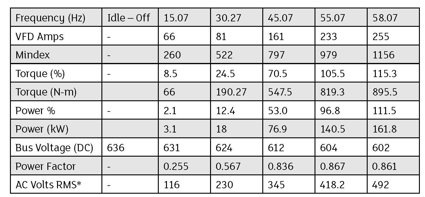 IMAGE 2: VFD PC tool data capture on pump start. NOTE: * AC volts RMS calculated from Mindex,<br /> inverter modulation index, and DC bus voltage as following: AC RMS voltage = DC bus voltage * Mindex / 1,000 / 1.414
The VFD history was full of current limit alarms between 53 to 55.5 Hz, which likely varies with the rheology of the pumped slurry fluid. The VFD basic parameters matched the motor nameplate, and the current limit was set at the 1.15 service factor of 257 amps compared to the nominal 224 amps of the motor’s full load amperes (FLA).
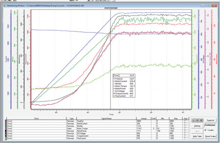 IMAGE 3: OEM VFD PC tool, variable trend capturing calculated torque versus output frequency.
The plant electrician and control room operator were told that the VFD was protecting itself and the motor by going into current limit regulation, which folds the output frequency back from reference command. Extended operation of the VFD at the current limit, which is above rated current of the motor, results in the motor thermal overload fault as parameterized.
The OEM PC tool software application was used to plot several variables and obtain a VFD calculated torque versus output frequency load profile, where output frequency is proportional to shaft motor speed rotations per minute (rpm).
Using the PC tool and its slider function (Image 3), the data shown in Image 2 was captured from a VFD-driven pump start. Image 2 data is shown at several output frequencies including where the VFD is in current limit regulation at 58 Hz.
Without reducing the frequency reference at the operator room after several minutes, the VFD tripped again on motor thermal overload. The VFD fault was acknowledged and reset after some time, and the operator reduced the frequency reference closer to 52 Hz, restarted the slurry pump and it ran fine.
The captured data from Image 2 was entered into a spreadsheet tool and added a trendline to extrapolate it to the unreachable frequency of 60 Hz (Image 4). It resulted in a second order polynomial, which was expected for a centrifugal pump, with R-squared value very close to one indicating a good fit.
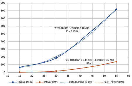 IMAGE 4: Data from Image 3 with regression trendlines for torque and power, X-axis in frequency (Hz)
Entering x = 60 Hz returns a required torque of 1,012 Newton-meters (Nm) and power of 186 kilowatts (kW), which equates to a 250-horsepower motor with 4 poles (1,785 rpm).
Unless the process rheology of the pumped slurry fluid changed or a parameter setting increase of the VFD current limit was programmed, the motor needed to be right-sized by an additional 25 percent. Reprogramming the current limit setting would operate the motor at or about its service factor rating, which compounded with VFD inverter overmodulation may result in excessive heat and reduced life.
A report was created and analysis was emailed to the plant electrician. It was explained that the no-load direct current (DC) bus voltage is typically 650 to 675 volts (V) when fed from a 480-V three-phase alternating current (AC) source.
In this installation, it was lower at 636 V DC, (Image 2 idle column) perhaps due to low-line conditions or adjacent load sagging the voltage on the plant secondary distribution step-down transformer.
At 55 Hz and above, the DC bus was sagged even lower from load resulting in the VFD operating into the overmodulation region. Most voltage source inverter VFDs operate on a desired volts per hertz principle, and the modulation index (Mindex) depth increases proportional to output frequency to keep the motor properly magnetized.
In this OEM VFD, and as in most, when Mindex exceeds 1,000 before reaching 60 Hz, it is usually an indication the AC line voltage is lower than nominal. In Image 3, the frequency output of 58 Hz has a VFD inverter Mindex of 1,156.
The green Mindex trace of Image 3 was linear through 55 Hz and steepened rapidly above this frequency to where it clipped at 1,156 at 58 Hz. This is the maximum Mindex (i.e., output voltage) for a VFD and results in the onset of the field weakening region if frequency were to further increase.
Keep in Mind
In summary, right-sizing the motor and potentially changing the plant secondary distribution voltage tap setting would allow the VFD output frequency to reach 60 Hz while avoiding current limit alarms, motor thermal overload trips, and the inverter over-modulation region.
If a VFD is not reaching frequency reference command while annunciating a current limit or experiencing repeated motor thermal overload faults, it is likely a load and motor mismatch. Using an OEM’s PC software tool or data from its keypad allows an analyst to empirically determine whether to right size the motor rated power.
