When pumping river or well water, abrasive particles—such as sand and other debris—erode hardware quickly. This leads to poor performance and costly, frequent repairs. Historically, sacrificial bronze components have been used as wear materials in these applications. However, the poor tribological nature of bronze requires generous running clearances between dynamic components, decreasing reliability from lack of rotor support. The lack of resistance to particulates in the media stream significantly shortens component life. A refinery in northeast Germany struggled with this problem in the water pumps of its collector wells. Designed and built in the early 1970s, the pumps had to be removed from service every two years because of bearing failures. To overcome this, the refinery elected to upgrade the bearings to a polyetheretherketone (PEEK)-based solution. Mean time between failure (MTBF) increased from two to more than five years as a result of the upgrade. This saved more than $135,000 (€100,000) in repairs. This case study discusses how this was achieved and the design process involved.
The Problem
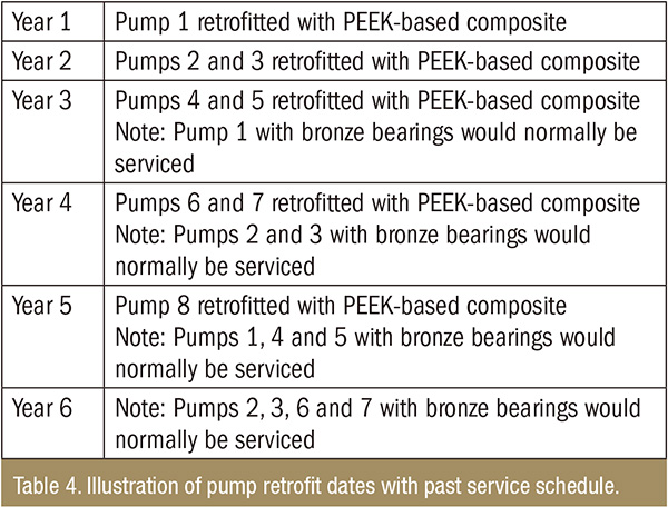
Sand, shells and other abrasive materials have been a problem for pump users for many years. These particles wear line shaft bearings, increasing clearances and leading to greater vibration and premature pump failure. In this application, water pumps designed and built in the 1970s were installed in refinery collector wells. Every two years, the pumps had to be removed from service because of bearing failures caused by erosion. The total costs were up to $13,500 (€10,000) per episode (see Table 1).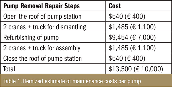
The Pumps & Bearings
The vertical water pumps operated at 75 to 90 kilowatts (kW), 1,480 rpm and pumped river water at a flow rate of 250 to 400 cubic meters per hour (m³/h) (see Table 2). Each pump had six line shaft bearings with inside diameters ranging from 60 to 65 millimeters (mm) (see Image 1).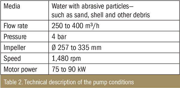
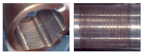 Image 1. The wear of a leaded tin bronze bearing on a 304 stainless steel shaft after eight hours of operation at 900 rpm and 25 psi (0.172 MPa) in 95 percent water with 5 percent silica sand
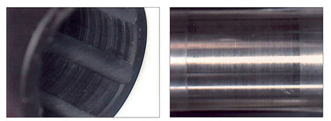 Image 2. The wear of a thermoplastic composite bearing on a 304 stainless steel shaft after eight hours of operation at 900 rpm and 25 psi (0.172 MPa) in 95 percent water with 5 percent silica sand
 New Bearing Material
Based on the failures, a new bearing material was required that could withstand off-curve and dry-run conditions, startup, high-impact vibration, and abrasive fluids. Low friction was also desired to prevent product flashing during upset. Because of these requirements, a chopped carbon fiber-reinforced, PEEK-based thermoplastic composite was selected. This material is thermally stable and can be used in temperatures up to 121 C (250 F) with a coefficient of thermal expansion 2.5 times that of steel. It is recommended for stationary components—such as bushings, line shaft bearings and bowl wear rings—in sump or river water pumps containing sand and other abrasives (see Table 3).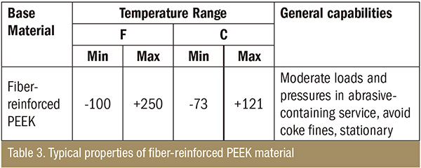
Design Considerations
At the German refinery, bearings were mechanically secured and designed with interference of 0.0015 mm/housing diameter with a minimum of 0.102 mm interference fit. For retrofit applications like this, the radial (or wall) thickness of the thermoplastic composite is generally dictated by existing hardware. For new equipment, however, standard practice is to design with a minimum radial wall thickness of 3 mm. If the part has internal grooves, radial thickness is measured at the thinnest portion of the cross-section. Use of a metal casing may be considered with a radial wall thicker than 6.35 mm. The thermoplastic composite bearing will generally have a surface finish between 1.6 and 3.2 Ra µm. A surface finish of between 0.4 and 0.8 Ra µm is recommended to be maintained on the mating metallic component. Typically, rounded axial grooves are recommended to help flush media through the bearing when abrasives are present. Spiral and circumferential grooves are an alternative to slow the flow of media through the bearing and assist with lubrication. Softer metals can show a high rate of wear when operating in low lubrication environments against this composite material. To maximize the life of the composite and mating components, a surface hardness minimum of 40 Rockwell C is recommended. For applications containing suspended solids, a higher hardness will maximize shaft life by reducing damage caused by hard particles scratching the surface. In these cases, dynamic surfaces should be treated to be harder than the abrasives being pumped. While thermoplastic composite materials are typically used in lubricated environments, sufficient lubrication is not present in some circumstances. Running clearances must be large enough to allow a fluid film to develop. Without the fluid film, efficiency and reliability improvements are eliminated and wear rate increases dramatically. Fluid flow also removes heat generated at the dynamic surfaces. Higher load applications may require more clearance for lubrication and heat dissipation. Despite these considerations, housing-to-shaft clearances are significantly reduced by using thermoplastic composites. Reduced clearances create a higher fluid film pressure, which leads to a more stable shaft with lower vibration. This creates a more reliable pump and reduces unplanned shutdowns resulting from process upset.Calculations
To determine ambient clearance (machine dimensions) for thermoplastic composites, values should be adjusted for the application temperature. This adjustment is based on the following calculation: Ambient Clearance = C + (A•B•D) – (G•H•D) + (E•F•D) A = ambient shaft diameter B = coefficient of thermal expansion (CTE ) for the shaft C = clearance according to American Petroleum Institute (API) 610 or equivalent standard D = change in temperature E = 2• radial thickness—or outside diameter (OD) – inside diameter (ID) F = CTE for the PEEK-based material G = housing/carrier ID H = CTE for the housing/carrier When properly designed, thermoplastic composites can be installed directly into pump housings or into metallic carriers.Results
In the five years since the German refinery upgraded eight pumps to thermoplastic composite components, none of the upgraded pumps have been removed from service because of bearing issues. MTBF increased, leading to a cost savings of approximately $135,000 (€100,000) during the past six years (see Table 4).