Today’s refinery fluid catalytic cracking (FCC) units use mechanical seals almost exclusively in their process pumps. Mechanical seals began to replace braided packing, which 60 years ago was commonly installed in the seal gland or stuffing box. The sealing components must be good for the operating temperature, and a suitable flush liquid must be introduced for cooling the shaft and its seals. However, using large amounts of flush liquid can be expensive. The flush liquid is a refined product, and after doing its cooling duty in a Flush Plan 32, it passes through the pump’s throat bushing into the less valuable pumpage. Overall economics are unlikely to favor Plan 32 in this instance. Users in slurry and light-cycle services are reassessing the total cost of Plan 32. In light-cycle oil pumps that use Plan 32, relatively large quantities of clean, externally supplied flush liquid end up in the light slurry being pumped. Due to widespread use of Plan 32 flush systems at a Caribbean oil refinery, hundreds of barrels per day (bpd) of refined product (gas oil) were lost to the coker charge, according to a former manager.
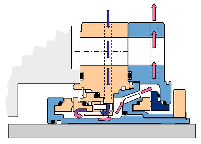 Image 1. A cartridge-style dual mechanical seal with bidirectional tapered pumping device. This style is suitable for many pumps in oil refineries. (Image courtesy of AESSEAL, Inc.)
Alternative Solutions
The former manager’s feedback was both catalyst and additional incentive for a U.S. oil refinery to re-examine seal selection and flush practices in its coker unit. This unit also experienced unremarkable—borderline—seal life, and the search for an optimized flush application merged into a quest for better mechanical seals and sound flush plan alternatives. A bit of research confirmed that metal bellows seals are favored for temperatures above 400 F. Below 400 F, pusher seals (seals that incorporate O-rings) would be acceptable. One such seal is depicted in the cross-section view of Image 1. A major seal vendor asked the refinery to consider gas- lubricated pump seals. (1) Gas-lubricated seals and upstream pumping seals force a clean external liquid into the seal face gap; such seals are said to incorporate “gas lift faces redesigned to positively pump seal flush fluid into the process.” In these seals, the pumping grooves are often only about 0.0003 inches/0.008 millimeters deep. When these grooves fill with solids, they no longer function as intended. The refinery decided not to pursue the gas lift and upstream pumping (liquid) seal options; these technologies may not be as widely applied on process pumps. Unlike modern steam crackers (ethylene plants), oil refineries can be cautious when it comes to applying new ideas. If profitable competitors use a particular mechanical seal geometry and flush plan, a refinery would rightly endeavor to duplicate the competition’s successful approach. As an aside, maintaining seal face cleanliness is a mandatory technical requirement for any industry segment and seal type used in process plants. Accordingly, experience checks are recommended. The best selection approach is to cultivate access to more than just one manufacturer. There are compelling reasons for having this multivendor access. The reasons have been widely published and solid arguments made for working with more than one seal manufacturer. (2)Best Practices Solutions
Following experience checks, it was ultimately recommended for Flush Plan 53 to incorporate a heat exchanger in the flush loop for services up to about 430 F at the U.S. refinery. This choice was supported by Plan 53 being successful in comparable services elsewhere. However, it was again noted that for pumps operating with temperatures substantially above 400 F, the heat load in a Plan 53 circuit may exceed comfortable limits and Plan 54 would be chosen instead. In an API Flush Plan 54, an external pump is used to circulate flush fluid in a closed loop. If maintained properly, this is a reliable pressurized plan. As for the U.S. oil refinery and its light-cycle oil pumps, at least one seal manufacturer favors conventional dual seals with a higher-pressure barrier fluid (depicted in Image 1). It and similar dual seals will work well in light hydrocarbon services with moderate temperatures. The seal design and piping plan must create the appropriate flow rate of barrier fluid to provide cooling for the seal faces. The flow must be distributed to cool both the inner and outer seal face pairs. Image 1 shows such designs. Depending on temperature, API Flush Plan 53 or one of its close derivatives is recommended and will achieve the desired effect of seal cooling and excluding the abrasive pumpage. A small and generally negligible amount of barrier fluid may still enter the pump and minimally dilute the product or process. The seal faces in Image 1 are well-cooled because the seal incorporates a high-flow (bidirectional) pumping ring and a baffle that directs fluid to circulate around—and thus cool— the inboard faces. A heat exchanger is sometimes used in the flush liquid loop, although the large diameter tapered pumping device, or an auger-like pumping screw, typically move the barrier fluid at flow rates greater than those achievable with traditional configurations. Bidirectional designs generate head and flow regardless of the shaft’s rotational direction.Will the Best Seal Fit?
Users may find in older pumps that the seal cavity cross- sectional clearance is probably only 3/8 inch and that some seal geometries may not be accommodated by the seal cavities. However, several vendors offer dual mechanical seals that could fit in the spatial envelope available in 1960s or 1970s pumps without reconfiguration of equipment. It should also be noted that many slurry pumps had their stuffing boxes modified decades ago after it was realized that solids tend to collect behind the throat bushing. Tapered stuffing boxes do not incorporate throat bushings. These tapered geometries and tapered bores are now widely used in applications where accumulation of solids in dead spaces must be avoided. Tapered bores can usually accommodate cartridge-style seals.3 Other stuffing box modifications are feasible and, in most instances, the cost is easily justified.Recommendations
The following recommendations for mechanical seals in FCC units are based on advice given to the oil refinery mentioned earlier in this case study and reflect considerable research. Trial and error solutions were attempted and the FCC pumps in question predated 1970. Among several other possible flaws, the owners had possibly overlooked that the troublesome pumps may have been sold with braided packing. Some of these old-style pumps were known to have rather slender shafts and braided packing acted as a stabilizing bushing for these shafts. This stabilizing effect may have been lost when packing lost its place to mechanical seals. Because of this, suitable remedial details were included in the list of recommendations given below. While these suggestions are specific to the refinery, other users may find them useful.- Establish formal communication with several seal manufacturing companies.
- Provide emails to the local representatives of each, with invitation to reply by a deadline date (typically one week).
- Provide API data sheet(s) to each of the four potential manufacturers or vendors.
- Request experience data whereby each manufacturer discloses proposed seal type and estimated or known average life attained.
- Make No. 4 a training experience whereby undesirable experimentation is disclosed as such. Accordingly, request feedback from the vendor who floated the idea of gas- lubricated and/or upstream pumping seals for the application 6at issue here.
- Request comments on any sealing system design elements (e.g., throat bushings that stabilize the shaft, “excluder” components that keep away solids, possible seal chamber modifications) required for the application.
- Provide a proposal drawing with a detailed bill of materials showing the basic seal design and sealing system requirements. Request each manufacturer’s comment on minimum required seal cavity dimensions. If warranted, involve seal manufacturers in your overall pump upgrade strategies or plans. In case a seal manufacturer is unresponsive or limits their interest to selling seals, consider involving a competent pump repair shop; emphasize that you seek feedback on stuffing box modifications.
- Compare seal leakage with vendor’s proposed flush plan against buffer fluid lost into pumpage (possibly a contractor or consultant calculation) to determine incremental savings.
- Request API Flush Plan number and/or modification recommendations to an existing flush plan. Be sure to become familiar with API Plans 53a/53b/53c and 54. 10Ascertain the heat removal rate (BTU/hr) if a cooler or heat exchanger is needed.
- Note that some pumping ring designs are considerably more efficient than others.
- Compare vendor-supplied data and look for deviations from standard, or customary, answers.
- Follow up on deviations and resolve differences between the answers submitted by different vendors.
- Bloch-Budris; “Pump User’s Handbook: Life Extension,” Fairmont Publishing Company, Lilburn, GA, 4th Edition, (2014), ISBN 0-88173-720-8
- Bloch, Heinz P.; “Petrochemical Machinery Insights,” (2016) Elsevier Publishing, Oxford, UK, and Cambridge, MA, ISBN 978-0-12-809272-9
- Bloch, H.P.; “Pump Wisdom: Problem Solving for Operators and Specialists”; Wiley & Sons, Hoboken, NJ; (2011) ISBN 9-781118-04123-9