
With easy access to electricity, electric motors are now an option for large pumps and compressors once powered by gas engines or turbines. Electric motors can be low-voltage [600 volts (V) or less] or medium-voltage (greater than 600 V). As end users rely more and more on larger electric motors, they face new technical challenges—including how to start the motor. When a large motor starts, it can draw from six to six-and-a-half times the motor’s rated full load current or motor inrush current. The resulting large voltage disturbances are unacceptable to utility providers and the plant power system. Operators must have an appropriate motor-starting strategy that aligns with the process and utility requirements while remaining safe, reliable, maintainable and efficient. This article details popular motor-starting methodologies, how they work and how they affect the motor. The article will cover mechanical equipment ranging from 250 to 7,500 horsepower (HP) and motor voltage from 2.3 to 13.8 kilovolts (kV).
Classifications
Common motor-starting methodologies are classified as fixed frequency (50 or 60 hertz) or variable frequency. Fixed frequency methods consist of direct-on-line (DOL) and solid state reduced voltage starters. Variable frequency starting consists of variable frequency drives (VFDs). While the DOL starting method is widely understood, motor manufacturers can build DOL motors with much lower inrush.Low Inrush Motors
Low inrush motors are standard DOL motors from an operational standpoint. They run at a fixed speed according to the utility frequency. The motors require protection relays and are limited in their number of starts. However, they differ in rotor bar construction.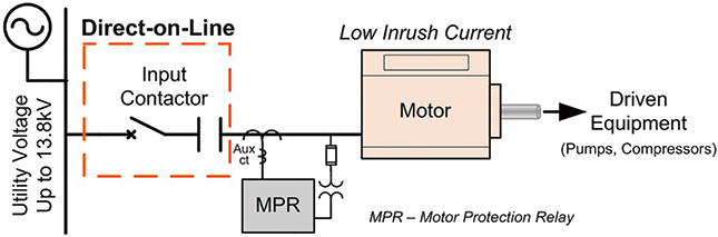 Figure 1a. Electrical one-line of a low inrush motor (Images and graphics courtesy of TMEIC)
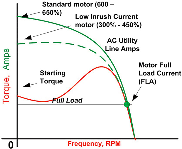 Figure 1b. Low inrush motor speed-torque/current profile
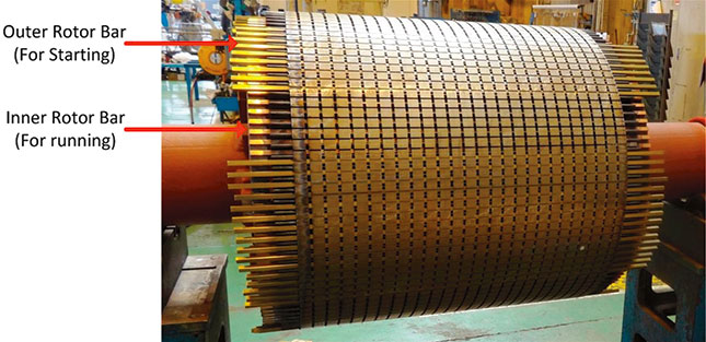 Image 1. Double-cage rotor bar construction for low inrush current motor
Reduced-Voltage Soft Starter
Reduced-voltage soft starters are the simplest and most common methods for reducing motor inrush current. Based on the silicon-controlled rectifier (SCR) developed in the 1950s, soft starters have been a low-cost motor starting solution since the 1980s. A soft starter uses SCRs to reduce the starting voltage and smoothly ramp up the voltage to the motor terminals without changing the power system frequency. Figure 2a shows an electrical one-line of a soft starter scheme. Similar to a household light dimmer, soft starters use a controller that allows for a timed ramp of output voltage and a programmed current limit. The output ramp sets the time during which the soft starter goes from zero to full voltage.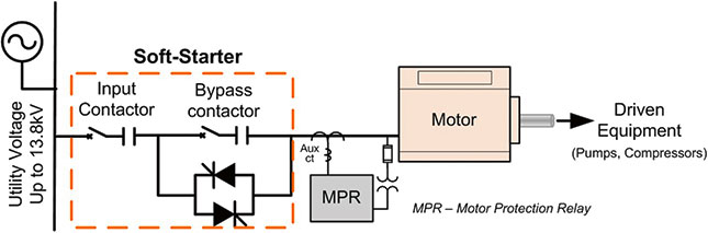 Figure 2a. Electrical one-line of a soft-starter
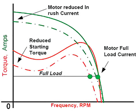 Figure 2b. Soft starter motor speed-torque/current profile
 - Driven equipment speed torque curve and system inertia
- Detailed motor data (if unavailable, the software can estimate from nameplate data)
- Upstream power system one-line that indicates the available short circuit power rating
- Power system voltage drop (utility specification)
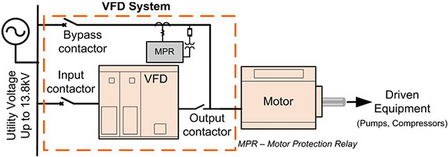 Figure 3a. Electrical one-line of a VFD
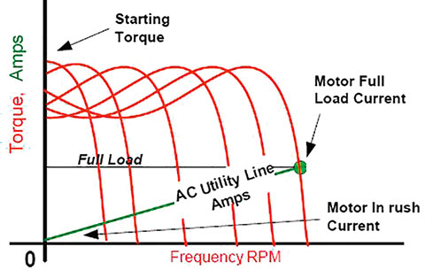 Figure 3b. VFD motor speed-torque/current profile
Variable Frequency Drives
VFDs convert fixed-frequency utility supply into variable voltage and variable frequency output.1 With a VFD, inrush current never exceeds the motor’s full load current. Figure 3a shows a VFD and a bypass arrangement for starting a large motor, and Figure 3b shows the motor speed-torque/current profile. According to Figure 3b, the inrush motor current should be able to ramp up from zero to the motor’s rated full load current. However, in practice, the VFD supplies the appropriate amount of current to start the motor and the load from standstill and to accelerate. VFDs have several other key advantages. They can vary the speed of the motor and have a high power factor across the entire speed range. They enjoy unlimited starts per hour while still providing energy savings for pumps and compressors. A smaller drive can be used with the VFD for starting only, reducing the initial cost. The drive reduces the load on the driven equipment and uses the momentary overload capability of the VFD. One VFD can start two or more motors sequentially and synchronize them to the utility line (see Figure 4). Each motor can leverage the benefits of a common VFD. This ability to use a common VFD reduces installation costs while still allowing variation of the speed on any one motor.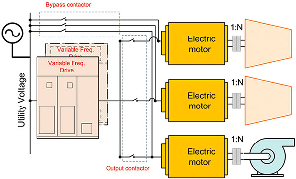 Figure 4. VFD for starting multiple motors
Selecting a Starting Strategy
Selecting the right starting strategy is critical to reaching targeted capital expenditures, planned revenue and total cost of ownership (see Figure 5). Except for VFDs, the available short circuit current and allowable voltage drop must be known for most starting strategies. Plant personnel should consider the process requirements, starts per hour, torsional effect on the driven equipment and motor power factor before selecting a motor-starting method.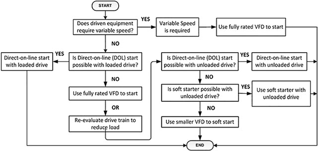 Figure 5. Flowchart for selecting a starting strategy
Techno-Economic Evaluation
Table 1 compares various starting methods. Cost factors are weighted against the DOL starting method, which uses neither a soft starter nor VFD and is the least expensive option available.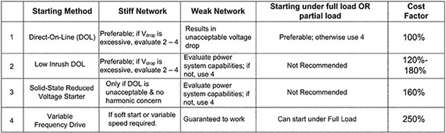 Table 1. Techno-economic comparison of different starting strategies