

Process and pipeline pumps in modern industry are usually designed and built in accordance with one of the three most prevalent industry standards for pumps.
In the United States, a combined American National Standards Institute/American Society of Mechanical Engineers (ANSI/ASME) document is widely used for pumps in water and aqueous (nonhydrocarbon) services. The primary aim of the standard is to allow the kind of dimensional interchangeability that permits insertion of a pump from Vendor A in the space originally occupied by products from Vendor B.
ASME B73.1 & ISO 5199
The widely referenced centrifugal pump standard known as ASME B73.1 can trace its origins to 1974 when, after combining and consolidating the ASME standard with a similar Hydraulic Institute (HI) standard, the two became ANSI B73.1. This new standard has been periodically updated and the current version is called “Specification for Horizontal End Suction Centrifugal Pumps for Chemical Processes.”
In the International Organization for Standardization (ISO) community where 50-hertz (Hz) power systems are the norm, ISO 5199:2002 represents a “Technical Specification for Centrifugal Pumps—Class II.” ASME B73.1 or ISO 5199 are not fully interchangeable; separation is based on the regionally prevailing electric power frequency, B73.1 for 60 Hz and ISO 5199 for 50 Hz. Both standards are widely referenced worldwide for centrifugal pump projects, even outside of chemical process applications. The core coverage of these standards encompasses single-stage end suction, centerline (self-venting) discharge, back pull-out and frame mounting. However, either standard can be useful in applications involving other frequencies—variable frequency drives (VFDs) in all types and sizes of process pumps.
Broadly speaking, the same thought processes govern the dimensional interchangeability limited to pumps made in compliance with ASME and pumps made in accordance with ISO standards. In either case, principal dimensions include, but are not limited to, the distance from base-mounting surfaces to the shaft centerline, and the elevations and distances from pump suction to discharge nozzles.
ANSI & ISO vs. API Pumps
ANSI/ASME and ISO-compliant pumps usually have their mounting pads (feet) incorporated in the casing’s base. The thermal rise of the shaft centerline of ANSI/ASME and ISO-compliant pumps can be as much as three times greater than that of centerline-mounted American Petroleum Institute (API) pumps. For many decades, the API has issued pump standard API 610 for products considered flammable, toxic or prone to explode under reasonably possible circumstances.
.jpg) IMAGE 1: A centerline-mounted, back pull-out, single-stage process pump (Image courtesy of Hydro Inc.)
IMAGE 1: A centerline-mounted, back pull-out, single-stage process pump (Image courtesy of Hydro Inc.)The emphasis of the API 610 pump standard is on strength, quality and reliability. API pumps are centerline-mounted (Image 1) and the stipulated distance between driver and driven shaft ends is 7 inches. Spacer couplings keep misalignment angles low and greatly facilitate back pull-out of hydraulic assemblies in need of exchange or repair.
Deciding Between Available Pumps
Experience-based selection strategies often follow the practices of Monsanto Chemical’s Texas City plant in the 1970s.1 Among these was the recommendation to use in-between-bearing whenever the product of power input and rotational speed [kilowatts (kW) x revolutions per minute (rpm)] exceeded 675,000.
Others adopted Monsanto’s practices.1 It was also recommended that API 610-compliant pumps be given strong consideration when one or more of these six conditions are reached or exceeded:
- head exceeds 350 feet
- temperature exceeds 300 F on pipe up to and including 6-inch nominal diameter; alternatively, if the temperature exceeds 350 F on pipe starting with 8-inch nominal diameter
- pumps with drivers rated in excess of 100 horsepower (hp), starting at 75 kW and higher
- suction pressures over 75 pounds per square inch gauge (psig)
- flow in excess of the best efficiency point (BEP) for the pump at issue
- speeds in excess of 3,600 rpm
Exceptions to the six conditions can be made judiciously. However, to qualify for such an exception, the pumped fluid should be nonflammable, nontoxic and nonexplosive.
In general, exceptions would be granted if the vendor demonstrated years of successful operation for the proposed pump in a comparable or perhaps even more critical service.
Best-in-Class Experience
Best-in-class (BiC) pump users are ones that obtain long failure-free runs from their pumps. BiCs have on their bidders’ lists only vendors (or custom builders) with proven experience records. Such pump vendors and manufacturers would be well established and would have recorded sound quality and on-time deliveries.
Exceptions taken by a bidder to the BiC owner-operator’s specification should be carefully examined for their potential reliability impact. This examination process serves as a check on the pump manufacturers’ understanding of the buyer’s long-term reliability expectations.
Because competent bidders employ a satisfied workforce of experienced specialists, conduct effective training and mentoring, and provide quality control and inspection departments, their products should command reasonable pricing. Reasonable pricing should not be confused with lowest pricing, although reasonable pricing may indeed be lowest in terms of life cycle cost projections.
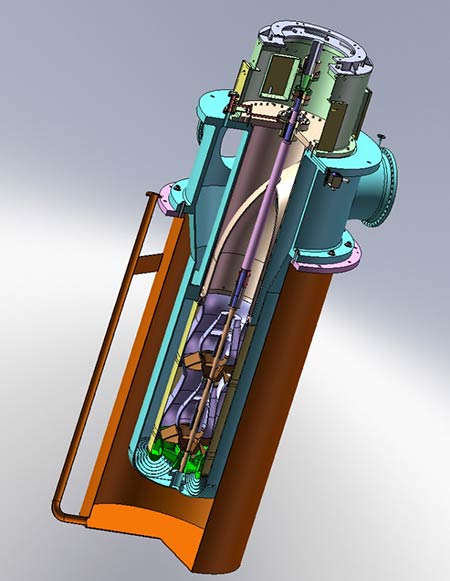 IMAGE 2: Custom-built vertical pipeline pump with drive motor removed (Image courtesy of Alfred Conhagen Inc.)
Vertical pumps are available in many hundreds of styles and configurations, and Image 2 shows a two-stage pump custom built for pipeline service. On this pump, the entire pumping element can be removed as one piece for maintenance. The motor mount (with the motor attached) would be removed first, 24 screws are removed next, and the whole pump is then lifted out.
It is an example of a design that is user-oriented in terms of maintenance and probable overall reliability.2
Both API and non-API standards are used in custom-built pumps, depending on user preference, type of service and prevailing experience. Competent designs are available not only from OEMs, but also from certain key custom design innovators and manufacturing specialists.
In all instances, the pump owner-operator would compile a specification document. The pump owner-operator or its designated project team would mail the document to at least two, but probably three or four, of these bidders or providers.
Their replies or cost quotes would be carefully reviewed. Whenever possible, these replies would describe the vendor’s offer pictorially.
The mechanical seal in Image 3 is typical of six or more add-ons that preferred vendor-manufacturers should be willing to provide in support of their desire to provide high-reliability products. They should have no reluctance to provide a listing of proven user experience.
Better Pumps
Anybody can buy a cheap pump. The term “better pumps” describes fluid movers that are designed beyond hydraulic efficiency and modern metallurgy. Better pumps are ones that avoid risk areas in the mechanical portion commonly called the drive-end. That part of process pumps that has been neglected most often and is where cost-cutting should cause the greatest concern.
Deviations from best available technology increase the failure risk. As three or four or more deviations combine, a failure is likely to occur. An analogy could be drawn from an incident involving two automobiles, with one driving behind the other. When the trailing vehicle traveled at (a) an excessive speed, with (b) worn tires, on (c) a wet road, and (d) followed the leading car too closely, a rear-end collision resulted. Had there just been any three of the four violations, the event might be recalled as a near-miss incident. Had there been any two of the four, it would serve no purpose to tell the story in the first place.
Too much cost-cutting by pump manufacturers and purchasers will negatively affect the drive-ends of pumps. Flawed drive-end components are therefore among the main contributors to repeat failures that often plague process pumps. Drive-end flaws should be addressed with urgency, and this article is intended as an overview of what guides BiC oil and gas companies in selecting better pumps.
Why Insist on Better Pumps?
Well-informed reliability professionals will be reluctant to accept pumps that incorporate risky drive-ends. The short overview of reasons is that reliability-focused professionals take seriously their obligation to consider the actual, lifetime-related and not short-term cost of ownership. They have learned that price is what one pays and value is what one gets.
As we make it our standard procedure to review pump drawings, we will quickly realize that not all pump manufacturers are on top of user experience. While at first glance the reviewer might see nothing wrong, we must remember that, in any given time period, approximately 7 percent of the pump population in U.S. oil refineries fails three to four times as often as that refinery’s average pump.
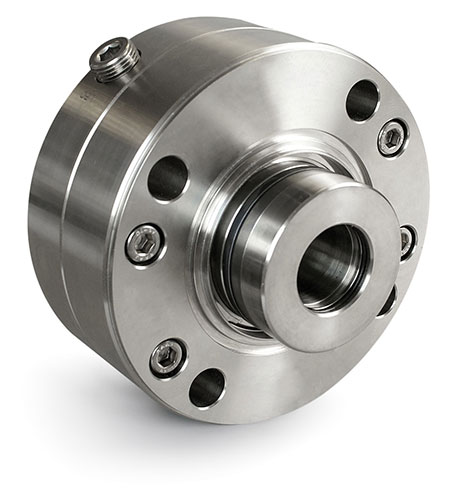 IMAGE 3: Cartridge-style dual mechanical seal suitable for many pumps and services in the oil and gas industries (Image courtesy of AESSEAL)
Whenever reliability professionals make it their practice to review pump drawings, they will uncover details as to why 7 percent of the total pump population fails relatively frequently and sometimes quite randomly. Drawings often show areas of risk and vulnerability that have been found and eliminated by BiCs.
Their subject matter experts have been instrumental in eliminating flaws in a specification and review process that includes a close examination and comparison of pump cross-sectional drawings and bills of materials.
Among the important vulnerabilities, deviations from best available technology or just plain risk areas, subject matter experts have found:
- Oil rings (intended to lift oil from the sump into the bearings) are incorrectly designed and/or manufactured.
- Back-to-back oriented thrust bearings are not located in a cartridge. Therefore, retrofitting flinger discs to take the place of deficient oil rings will not be possible.
- Bearing housing protector seals are inferior to the ones representing best available technology. Bearing housings lack oil drain holes from locations where trapped oil will overheat and deprive bearings of proper lubrication.4
- There is uncertainty as to the type or style of constant-level lubricator that will be supplied. Unless specified, process pump manufacturers will often provide the least expensive constant level lubricator configuration.
- Each issue merits further explanation and additional ones exist.
References
1-Ingram, J.H., “Pump Reliability—Where do you Start,” presented at ASME Petroleum Mechanical Engineering Workshop and Conference, Dallas, Texas, Sept. 13-15, 1981.
2-Alfred Conhagen Inc., La Marque/Houston, Texas
3-Bloch, Heinz P., “Pump Wisdom: Problem Solving for Operators and Specialists,” (2011), John Wiley & Sons, Hoboken, New Jersey, ISBN 978-1-118-04123-9
4-Bloch/Ehlert/Geitner; “Optimized Equipment Lubrication, Oil Mist Technology and Storage Preservation,” (2020) Reliabilityweb, Ft. Myers, Florida
