

Combined-cycle gas turbine (CCGT) power plants present difficult challenges for pumps and associated equipment, such as valves and seals.
High operating temperatures and pressures are characteristic of many applications operating within CCGT plants. CCGT plants are also expected to handle rapid load variations and are required to start and stop frequently. As a result, the pumps must be designed and selected to handle severe transient operating conditions.
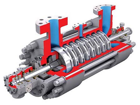 IMAGE 1: Diffuser ring-section pump (Images courtesy of Flowserve)
 A typical combined-cycle plant may have between 50 to 100 pumps. These pump types typically include:
- multistage, between bearings, ring-section pumps (BB4)
- vertical, wet-pit, single-stage pumps (VS1)
- vertical, canned, multistage pumps (VS6)
- horizontal, single-stage, axially split pumps (BB1, BB2)
- general service end-suction pumps (OH1)
- high-pressure and temperature end-suction pumps (OH2)
- sump pumps (VS4, VS5)
- liquid ring vacuum pumps
This article focuses on several critical services in combined-cycle plants: main feedwater, condensate extraction and condenser cooling.
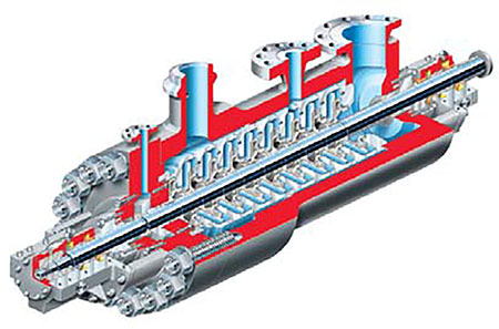 IMAGE 2: Double-case barrel pump
Main Feedwater Pumps
The purpose of a main feed pump is to deliver feedwater from the low-pressure (LP) drum to the economizer inlets of the intermediate-pressure (IP) and high-pressure (HP) sections of the heat recovery steam generator (HRSG).
Multistage, inline diffuser, ring-section pumps are most typically specified for this service in combined-cycle plants.
Occasionally, customers will specify a double-case design for these applications.
Boiler feedwater is chemically treated to a high purity level, making it more corrosive than untreated water. As a result, the fluid-handling components (e.g., stage casings, diffusers and impellers) that see high fluid velocities must be provided in 12 percent chrome (CA6NMN) to avoid erosion-corrosion damage.
On higher-pressure applications, the suction and discharge heads are also recommended to be in 12 percent chrome. Laser hardening or direct laser deposition (DLD) at running fits can be offered to make the pump resilient to damage that may be caused by transient operation, including loss of suction pressure. The laser-hardening treatment only hardens the outer surface of the part; the base material remains unchanged.
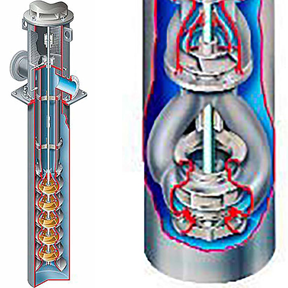 IMAGE 3 (left): Condensate pump with a single-suction, first-stage impeller.
IMAGE 4 (right): Double-suction, first-stage condensate pump
The result is a reliable, ductile part, with maximized surface hardness, which is the ideal blend of part characteristics. DLD is a welding process that metallurgically bonds a metal powder to the base material. Due to a controlled and localized heat input, this process can be applied to various base metals without distortion or the need for post-weld heat treatment.
Suction performance, while important for all pumps, is a concern for high-energy pumps in boiler feed service.
The net positive suction head available (NPSHa) is limited by the physical height of the suction vessel, but certain NPSHa and NPSH required (NPSHr) margin ratios must be maintained to achieve optimum performance and long life. The first-stage impeller is selected with particular care and often features a larger suction eye or, in some cases, a double-suction design.
The pumps offer an intermediate takeoff connection to provide flow to the IP section of the HRSG. Boiler feed pumps are subject to sudden load swings and operation at numerous operating conditions. As a result, the typical bearing arrangement is sleeve radial bearings and tilting pad-type thrust bearings on applications exceeding 4,000 horsepower (hp).
With this type of arrangement, a forced feed lubrication system is used. On lower hp applications, other bearing arrangements may be considered.
Feed pumps may be direct drive or variable speed drive with the use of fluid couplings or variable frequency drives (VFDs).
The most common configuration is 2 x 100 percent per HRSG.
Condensate Extraction Pumps
Condensate extraction pumps are used to pump condensate from the hot well of the condenser to the inlet of the LP economizer of the HRSG. The most common configurations are 2 x 100 percent or 3 x 50 percent capacity pumps per condenser (not per HRSG).
The first-stage impeller design is critical, as condensate pumps are required to operate with low NPSHa. The condenser operates at a vacuum of approximately 0.65 pounds per square inch absolute (psia) bar (0.045 bar absolute). The condensate is near its vaporization point with a typical temperature of 35 C to 40 C (95 F to 105 F). This means the NPSHa at the liquid level in the condenser hot well is zero. As a result, a canned vertical multistage pump is typically selected for
this application.
The setting or length of the pump must provide sufficient NPSH to the first-stage impeller. Smaller CCGT plants use a vertical, multistage canned pump, with a single-suction, first-stage impeller. On larger plants, a double-suction, first-stage impeller can reduce the pump length and should be considered on applications exceeding 4,000 gallons per minute (gpm) per pump.
For reliable operation, the design for the first-stage impeller should include:
- suction-specific speed (NSS) lower than 12,000 to ensure flow stability over a wide range of operation
- an impeller inlet peripheral velocity (inlet tip speed) that is below 70 feet per second (ft/s)
- cavitation-resistant material, such as 12 percent chrome
Due to the high pressure on this critical application, a cartridge-style mechanical seal is recommended to seal the fluid pumps. The associated pump-sealing systems must stop air from entering the pump when on standby under a vacuum. API Plans 13 and 32 accomplish this.
Condenser Cooling Water (CCW) Pumps
All thermal power plants eject large amounts of heat to the environment, and a CCGT plant is no exception. A typical combined-cycle plant with a 57 percent thermal efficiency will eject 43 percent of the heat input by the fuel. About 9 percent will go out the HRSG stack. The rest is removed by the cooling water pumped through the condenser.
Condensers have traditionally been cooled by water using either once-through or closed (cooling tower) systems. The cooling water requirement of a typical CCGT plant using a cooling tower can be estimated at about 250 gpm per megawatt (MW). As a result, a 750 MW combined-cycle plant will require a cooling water flow of about 187,500 gpm, which would normally be shared between two pumps.
Environmental requirements in many regions no longer allow once-through cooling from rivers or lakes. Even conventional wet-cooled cooling towers can be an issue, as water withdrawals are still required to make up for blowdown as well as evaporation and drift from the tower. As a result, air-cooled condensers are becoming more common. Their initial capital cost is much higher and plant thermal efficiency may be reduced by as much as 3 or 4 percent in high ambient temperature locations.
The most frequent choice for this application is a vertical, single-stage pump with a semi-open impeller.
However, depending on end user specific preference, single-stage, double-suction horizontally split, or concrete volute pumps may be used.
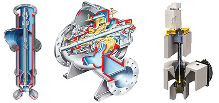 IMAGE 5-7: Condenser cooling water (CCW) pump types
CCW Pump Types
Regardless of the construction type, these critical items must be reviewed to ensure optimum and reliable performance under all operational modes:
- Ensure there is ample submergence from the low-water level to suppress vortexing and provide sufficient NPSHa to prevent cavitation at the maximum flow or runout condition.
- Evaluate material options for all critical components, particularly when handling either brackish or seawater. Material options range from coated carbon steel to super duplex. When handling seawater or other high-chloride solutions, a stainless-steel alloy with a pitting resistance equivalent number (PREN) greater than 40 should be considered. (The PREN is a measure of the relative pitting corrosion resistance of stainless steel in a chloride-containing environment.) The elements that have a significant impact are chromium (Cr), molybdenum (Mo) and nitrogen (N). The PREN formula, which quantifies their respective contribution, is shown in Equation 1: PREN = 1 × %Cr + 3.3 × %Mo + 16 × %N
- Higher PREN values indicate greater corrosion resistance.
- When evaluating materials, the first cost, while important, should not be the only factor. The total life cycle cost of the equipment should be considered.
- The performance and reliability of these high-flow CCW pumps are greatly affected by the design of the intake structures in which they are installed. Stable pump conditions require a uniform distribution of the flow approaching the pump suction inlet. Hydraulic Institute Standard ANSI/HI 9.8-2019 “Rotodynamic Pumps for Pump Intake Design” provides guidelines for pump intake designs. One of the most proven methods to predict performance of an installation is to duplicate it with a physical scale model test.
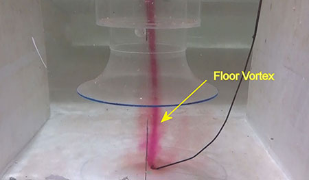 IMAGE 8: Actual model intake test showing a floor vortex (Image courtesy of Clemson Engineering Hydraulics, Inc.)
Conclusion
This article has focused on CCGT power plants that use high-temperature exhaust from the gas turbine as the source of heat for steam generation. Any power plant using a Rankine cycle with steam as the working fluid—whether the source of the heat is coal, biomass, oil, trash or the sun—includes the same pump services, and the issues discussed herein should be properly evaluated.
