

In part 1 of my column in the November 2022 issue, we covered the first parts of making a decision if you should buy a slower pump. We hit on measuring, the decision process and more.
Specific Speed (Ns) & Suction Specific Speed (Nss)
Specific speed (Ns), in its simplest definition, addresses impeller geometry, including vane angles and the number of vanes. In the pump, both dynamic and static forces and their ratio are functions of specific speed (F dynamic ÷ F static).
Note that specific speeds of approximately 3,000 will yield the most efficient pump, and, in a head coefficient versus specific speed comparison, it peaks around 1,000. You can generate pump head easier at lower specific speeds but not as efficiently at higher specific speeds.
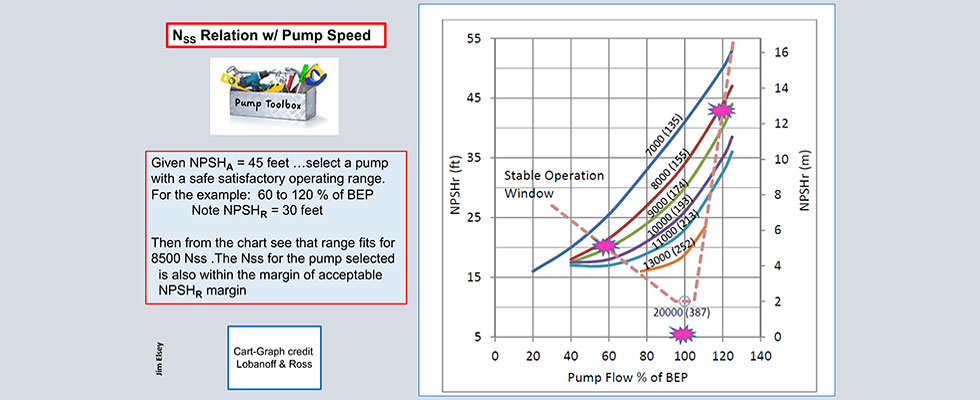
As suction specific speed (Nss) increases, the stable/allowable operating envelope for the pump decreases. The pump suction condition is really the most important factor to examine when considering pump speed. While NPSH margin is paramount, you can do yourself a favor by determining the allowable pump operating region (window of stability) for your selection from proposed sample performance curves.
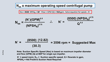
From that, you can estimate the maximum suction specific speed you decide to operate with. Knowing the maximum suction specific speed, you can then determine the maximum speed for the pump utilizing the suction specific speed formula solved algebraically for speed (N). For example, assume a maximum suction specific speed of 8,500. Do not confuse the suction specific speed of 8,500 as a maximum; this is just an example.
Mitigating & Dynamic Forces
Suction energy (SE) is another often overlooked parameter. SE is, in essence, a measurement of the liquid momentum at the impeller eye. Column space does not allow for a full explanation here, so please refer to my May 2020 column for more details.
While looking at the liquid velocity on the suction, also look at the velocity at the discharge nozzle and 6 diameters downstream. See American National Standards Institute (ANSI)/Hydraulic Institute (HI) standard 9.6.6 for best practices, but know that over 8 to 10 feet per second on the suction side is approaching potential issues. Here, slower is better. I appreciate that impeller vane tip speeds would be similar for either case (a larger, slower pump versus a smaller, faster one), but I am suggesting the alternate idea that it may be better to add another stage to the pump, if you require additional head, and to change the impeller width, if you need more flow. Another solution could be two pumps in series.
Nominal limits for maximum impeller diameter are normally 27 inches for 4 pole and 13 inches for 2-pole speed limits. This limiting factor is independent of the liquid properties and is based more on the material strength of the impeller (shrouds and vanes). Excess tip speed will manifest as unacceptable vibration. The radial forces are a function of the impeller geometry for a given casing design and will increase directly with speed. Radial forces will have a direct impact on shaft deflection that directly affects bearing and mechanical seal life. Note that a deflecting shaft at 4-pole speeds will deflect 3,550 times per minute and 7,100 times per minute at 2-pole speeds. The quality of the impeller manufacturing process will affect both hydraulic and mechanical balance. Bearing wear, mechanical seal life and driver alignment will all become more critical with increased speed.
Axial forces are a function of impeller geometry, suction pressure, clearances and developed head. Deleterious effects from axial forces can be exacerbated by a loose fit of the impeller to the shaft. Axial thrust increases proportional to speed. Frequencies of the rotor dynamic forces depend on speed and flow and react proportionally.
Inertia
Pumps with larger impellers and a larger rotating mass will possess higher inertia. Higher inertia translates to both a longer coast down on loss of power and a longer time to reach full speed during startup. This delayed reaction property is beneficial for controlling transient system pressures, as the pump will slowly decelerate after a pump trip or control valve repositioning, yet it will continue to move the fluid. The slower reaction of hydraulic change will minimize column separation in downstream piping that reduces water hammer and other negative related actions.
Other Factors
What are some basic parameters and questions to consider when deciding on pump speed? I do not have the space to explain how each of these factors will affect the pump speed decision, but the following list is considered worthy of examination:
A rheology overview which includes all of the liquid properties and especially the amount of solids. The more solids present, the more you need to slow down. Also note abrasiveness, shape and size of the solids.
Viscosity is a liquid property many people overlook, so I highlight it with its own category. Higher viscosity requires a larger pump for the same hydraulic conditions.
Is the fluid Newtonian or non-Newtonian? Think shear and shear rate factor. Many non-Newtonian liquids do not react well to higher speeds.
In consideration of the actual duty cycle, it is important to quantify the cost of power (at some cost per kilowatt hour).
Suction conditions were discussed earlier, but also consider if it is a flooded suction versus a suction lift situation or if there are multiple pumps piped in parallel or series. The level of sophistication for the design of the suction system piping geometry is important to consider for critical submergence, turbulent flow, suction energy, suction nozzle velocity and NPSH margin.
Another important subset of suction conditions is if the pump is a self-primer. Note that the priming time on high-speed applications will heat the liquid in both the seal and priming chambers 8 to 10 times faster.
The following questions will also affect your choice of pump speed:
- What is the head and flow for the pump?
- Where on the performance curve relative to best efficiency point (BEP) is the condition point?
- Where does the system curve intersect the pump curve?
- What are the future system requirements?
- How will the system curve change with age?
- What is the minimum flow rate?
- How large is the safe operating envelope/the allowable operating area?
- The type of pump will have a big influence on the speed decision. Is the pump ANSI, API or other?
- Is the pump of a special design, such as low flow, high head or recessed impeller?
- Is the pump variable speed?
- Is the pump driven by an internal combustion engine (must be derated in many cases)?
- Is the pump driven by sheaves/belts or chains (shaft is side loaded)?
- How close is the brake horsepower (BHP) per 100 rpm limits of the shaft and bearing system?
- What is the site elevation above and or below sea level?
- Is the pump end suction OH1 type or between bearing (BB1)? Does the shaft interfere with the impeller eye area?
- Is the pump horizontal or vertical?
- Does the pump have dual or single volute or a diffusor?
- Is the pump impeller centerline concentric/congruent with the casing centerline?
- What is the pump impeller inlet tip speed, the amount of vane overlap and the liquid’s specific gravity?
- How many stages in the pump?
- Does the pump have a robust base and foundation?
- Is the pump properly grouted?
- How much pipe strain or nozzle loading is present?
- What type of lubrication system does the pump use?
- What type of bearings are used?
- Does the pump experience rapid temperature change?
- Does the pump operate a high or low temperatures?
- If the pump fails, what are the effects on the plant?
General Summary
Where did the urban myths relative to pump speed initiate? Many of the initial designs for high-speed pumps of the 1960s were based on the lower-speed models that simply had their speed increased to meet market demands. After some operational time, these pumps were frequently found unreliable. Why? Because many of the older pump models were not originally designed to operate at higher speeds. The subsequent failure events skewed the reliability data, so the common line of thinking that slower must be better prevailed. However, in the 1970s, the pumps that were redesigned and properly maintained to operate at higher speeds were often found to be just as reliable as slower-speed pumps from the previous design generations.
The caveat is that later model, high-speed pump designs come with added baggage in that they must be operated and maintained at superior standards. Higher levels of precision maintenance are required for pump reliability at faster speeds, such as proper rotor balance and operational clearances in conjunction with mitigation of pipe strain, establishing and maintaining precision alignments and other industry best practices.
As system head requirements increase, the laws of physics will force you into higher-speed pumps. However, I have witnessed several applications where a 1,750 rotations per minute (rpm), two-stage pump was the better choice over a single-stage, 3,550 rpm pump.
Caution: You can also operate a pump too slowly and have issues with hydrodynamic stability or overheating the motor due to cooling fan issues. I do not recommend operating most pumps below 600 rpm for any length of time unless the pump was designed or approved for those conditions. Check with the OEM in all cases, including the motor OEM.
In closing, I suggest a scenario where sometimes the road (think pump system) to your destination is built for multiple lanes of high-speed traffic. Think German autobahn (Bundesautobahn). However, sometimes there are just two lanes that can be approached slow and steady to get the job done with high reliably and enjoyment. Think 17 Mile Drive, Pebble Beach, California.
References
Centrifugal Pump Hydraulic Instability EPRI Report CS-1445 Research Project 1266-18 by Dr. E Mackay 1980
