

Part 2 of this article will be featured in an upcoming issue of Pumps & Systems.
Two of the top priorities for engineers designing piping systems include being on time and on budget. But these are secondary to meeting the system’s design requirements. Whether there is a heat transfer requirement for reacting components, flow rate requirements for system supply, or hydraulic grade line (HGL) requirements to avoid elevation issues, design is defined by requirements.
During the design phase, engineering work like pulling product specifications, sizing equipment and ensuring a conservative safety margin takes up much of the design process. The limited time pressures design choices, often leaving pipe size as an under-considered parameter.
Though pipe size generally informs the foundation of a design (informing velocities, pressure drop, equipment, fittings, costs), pipe size usually will not get the attention it deserves. As any deviation in pipe size essentially resets much of the engineering work from the original pipe size, varying pipe size can be time-consuming. However, exploring implications of pipe size on system design, operation and cost has the potential to improve designs and approach an optimized system.
Why Consider Pipe Size at All?
Recent trends in design have begun looking at designing systems holistically. While improvements in efficiency have largely focused on performance, attention has begun shifting to improving the system design. Analyzing components like pumps, valves and pipes as an interrelated matrix opens up many opportunities to improve a system’s operation and efficiency.
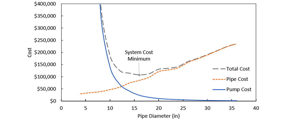
For example, the relationship between pipes and pumps creates many economic trade-offs to consider. While a smaller pipe has lower capital costs, the larger pump required to overcome the additional pressure losses will cost more (both in capital and long-term operating costs). Meanwhile, a larger pipe costs more upfront, but enables lower operating costs as the pump does not need to work as hard. Even with this simple example, it is clear there is a point where a perfectly sized pump paired with a perfectly sized pipe can minimize system costs. This point can be seen visually in Image 1. Each pump-pipe pair is informed by the essential design requirements, placing each potential component pair on equal technical footing.
If a perfect pair of pipes and pumps exists for any design requirement, why aren’t all hydraulic designs pursuing this optimal combination? Deadlines.
A History Lesson
To understand how system design reached its current state, look at the history of hydraulic design. The earliest ancestor, still sometimes used today, relies on hand calculations and handbooks. A collection of precalculated head loss for all sorts of pipe sizes and flow rates easily informs the frictional head to overcome during pump sizing. These handbooks were useful in eras when computers were larger.
While handbooks are a better alternative to calculating frictional head loss by hand, they can be limiting. For example, say the design’s required flow rate doubles, or the viscosity used for initial sizing was inaccurate, or pipe scaling on an existing system affects the frictional loss on each pipe. While an engineer can anticipate many considerations, any factor that is not considered requires new values from the handbook to perform new calculations. Hopefully, the calculation does not change so much that the pump specification has to be canceled. These uncertainties in design input require conservative design margins, leading to oversized equipment that costs more upfront and costs more to operate. While it is a shame to see a control valve controlling an oversized pump, many engineers would rather pay the additional costs over the life of the system than build a system that cannot meet its requirements.
With the effort to design a system that works while avoiding being excessively conservative (and therefore excessively expensive), it is no wonder pipe size is a set-and-forget parameter. Any change in pipe size can require a lot of duplicated efforts, leaving potential savings and improved operation on the table.
Spreadsheets: The False Prophet
There are several reasons most young engineers have never even seen a hydraulic handbook: they are not flexible, they take up valuable engineering time to pull values and they can lead to excessively conservative designs. Luckily, all engineers make use of the best calculator Bill Gates can offer: spreadsheets.
Spreadsheet sizing is a popular alternative to handbook calculations and is a good option when doing hydraulic design. Spreadsheets improve calculation flexibility by automatically updating results when input parameters change, reducing time spent on tedious calculations. Since calculations are updated automatically and follow the same basic form, it is easier to model more complicated systems. If an engineer builds an impressive spreadsheet, it can live on as the standard for years.
However, spreadsheets (and the humans that develop them) are far from perfect. Anyone that has ever found an error in a calculation spreadsheet can empathize with the pain and suffering associated with going cell by cell, formula by formula to find a typo or a missed reference. Not only does this troubleshooting take time away from analysis and other valuable engineering work, but it also throws the credibility of results into question. Spreadsheets make visualizing results difficult, again taking valuable engineering time to get results into an easily understandable form.
While pipe size is more easily varied in spreadsheets than in hand calculations, spreadsheets still have their limitations. For example, spreadsheets must be developed independently for each system, providing opportunities to introduce error. These systems must be simple, often avoiding the additional iterative solving required by something like a bypass loop or a cooling loop system. While designing a single operating case for a system is easy, it can be difficult to manage diverse operating conditions or explore the implications of scaling or increased friction with a spreadsheet. Since system design is iterative, results impact input that impact results. Ensuring each scenario is working with identical input can be its own management challenge.
The Rise of Modeling Software
Spreadsheets leave room for improvement in report-ready-result visualization, scenario management and overall input flexibility. With this opportunity to improve analysis, many suites of flow modeling software have entered the market to close that gap. Adopted in nearly every engineering industry, flow modeling software allows the calculations to get out of the way so engineers can focus on the analysis of design alternatives instead.
With calculation management sorted, 100-pipe systems can be modeled in a workday with every possible operating condition accounted for. While it is easier than ever to make permutations of a design, the limiting factor during pipe sizing again comes down to time.
To understand the challenge of pipe size optimization, look at an example. Imagine a simple system with a single pipe into and out of a pump between two reservoirs:
- Design requirement: Flow through pipe
- Limitation: Pump cannot add more than X amount of head
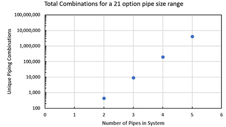
- Pipe candidates: Standard ANSI steel range from 1/8 inch to 18 inches (21 options)
- Goal: Minimize life cycle cost over five years
Based on the range of pipe sizes alone, there are more than 441 unique combinations to consider. As before, one of these 441 combinations will minimize the system’s life cycle cost as intended. However, relying on human judgment and limited engineering time to explore each of these combinations makes manual optimization impossible, regardless of the modeling tool’s calculating capabilities.
As one can imagine, the complexity of pipe size optimization increases exponentially as the number of pipes increase. As Image 2 shows, adding a third pipe increases the potential combinations to 9,261, a fourth pipe increases it to 194,481 combinations, a fifth pipe goes into the millions of combinations. Now, what about making a 100-pipe model in a day? With the specified standard ANSI steel range, a 100-pipe system would have 1e130 possible combinations. Optimizing pipe size by hand for a 100-pipe system is like finding a needle in a haystack—a haystack with ten duoquadragintillion combinations.
Sharing the belief, “Don’t let the perfect be the enemy of the good,” it is no wonder engineers do not take the time to optimize pipe size. Despite this, consider the benefits an adequately sized network can offer.
